Eureka AIR delivers breakthrough ideas for toughest innovation challenges, trusted by R&D personnel around the world.

Sealing mechanism

a sealing mechanism and sealing medium technology, applied in mechanical devices, instruments, weighing auxiliaries, etc., can solve the problems of unfavorable creep effect, overloading of individual components or regions of weighing sensors or scales, and complicated structure of sealing with the medium to be fed (e.g. compressed air)

Active Publication Date: 2013-09-03
WIPOTEC WIEGE UND POSITIONIERSYSTEME GMBH
View PDF14 Cites 11 Cited by
  • Summary
  • Abstract
  • Description
  • Claims
  • Application Information

AI Technical Summary

Benefits of technology

[0006]The present invention is therefore to provide a sealing mechanism for the reliable sealing of a scale housing in which the previously mentioned disadvantages are eliminated. This is achieved by an innovative sealing mechanism.
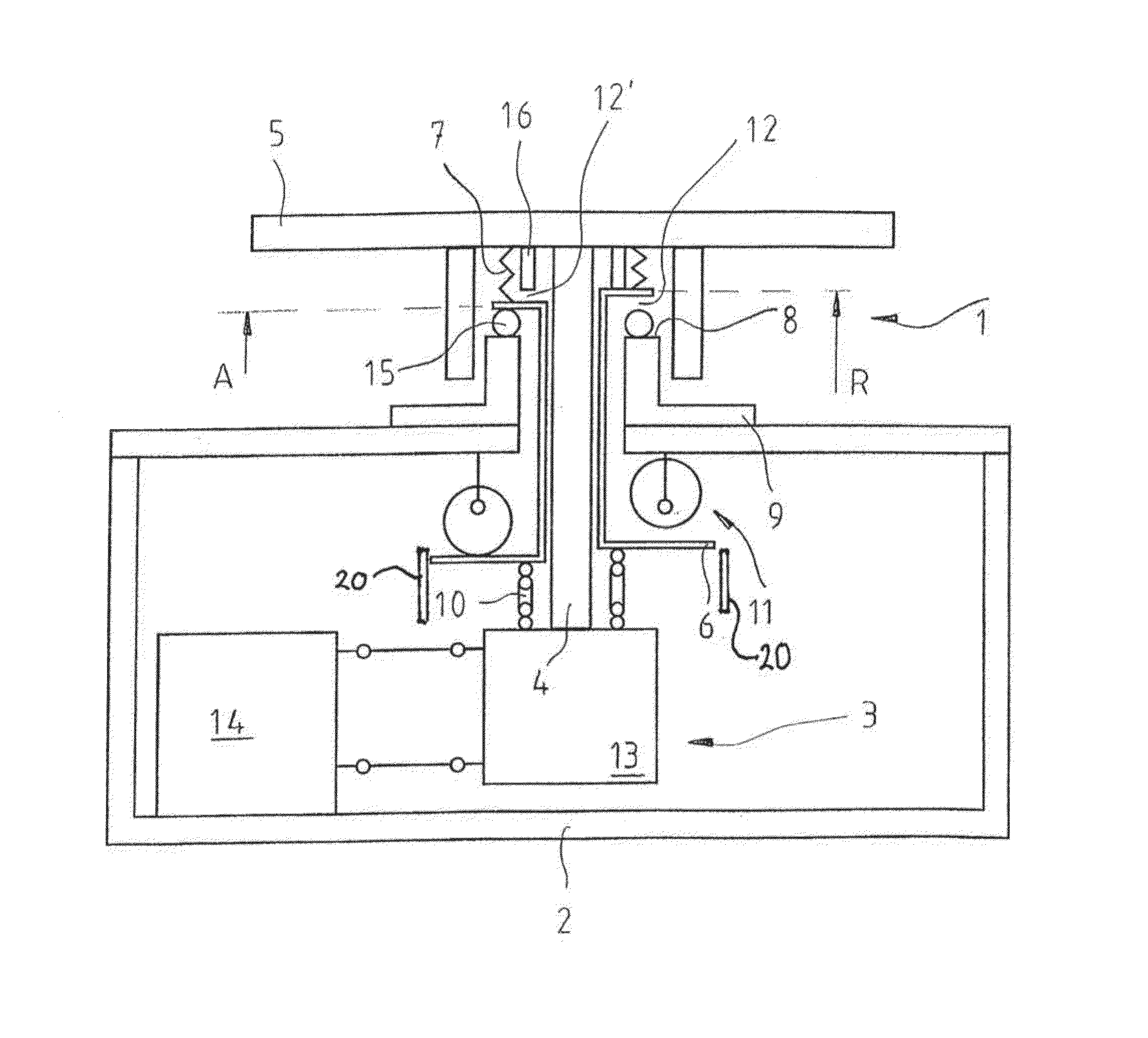
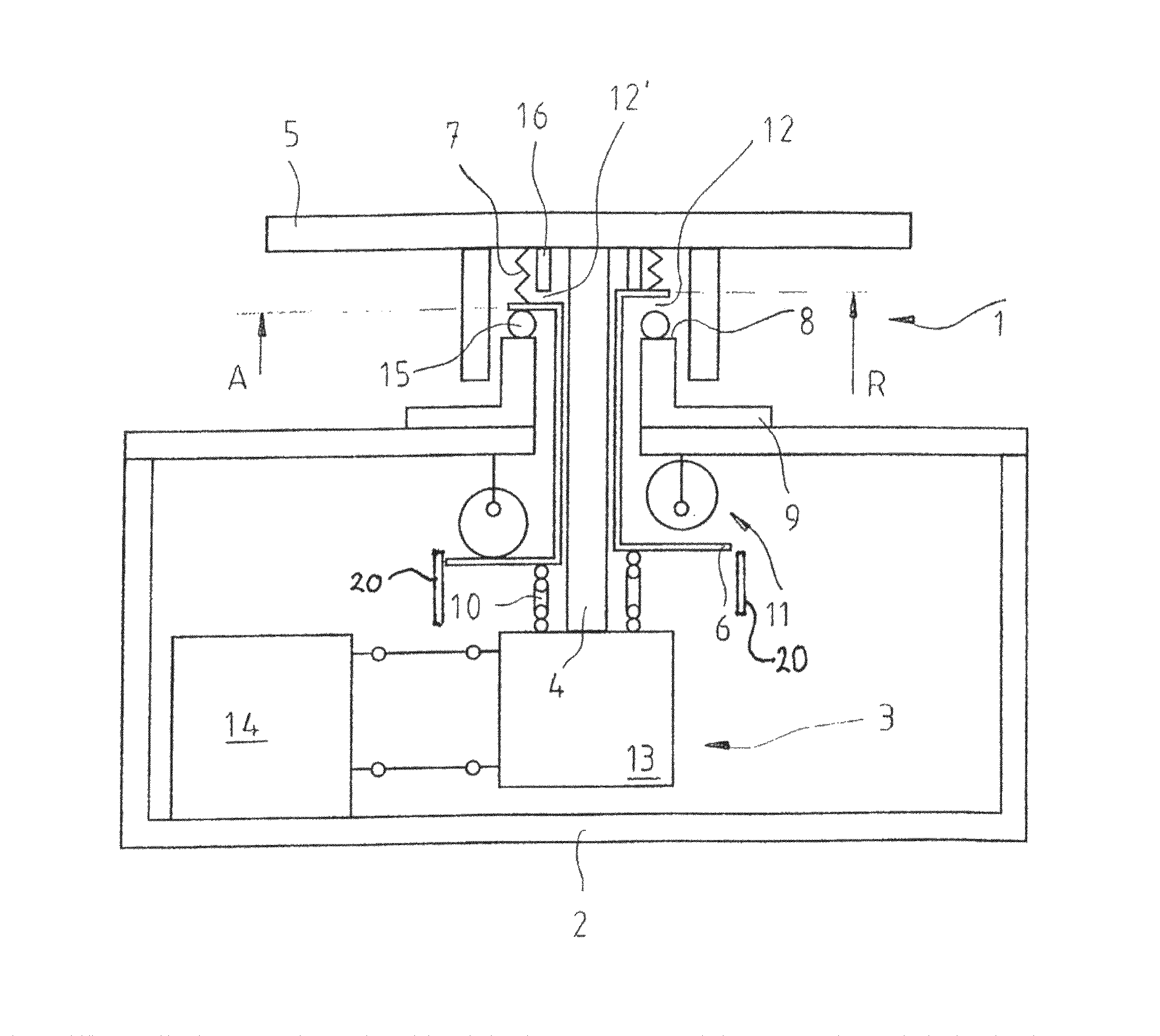
[0007]The invention is based on the knowledge that a sealing effect protecting a weighing sensor particularly well can be generated with the help of a lifting element. In one operating position, this interacts with the housing to form a seal, while it is connected only to the load receiver in a non-sealing rest position. This produces the advantage that a contact force for achieving the sealing effect can exist between the lifting element and a component of the housing, without this contact force simultaneously acting on the weighing sensor or the mechanism.

Problems solved by technology

The charging of the seal with the medium to be fed (e.g., compressed air) is structurally complicated and expensive.
Disadvantageously, for this seal, the load receiver is loaded with a spring force that is (considerable under some circumstances) introduced directly into the weighing sensor.
The corresponding mechanism is loaded accordingly, which can also lead to overloading of individual components or regions of the weighing sensor or the scale.
Undesired creep effects could be the result.
Also, an electromagnetic compensation of this force introduced into the sensor could be undesired and could require, under some circumstances, high compensation currents.
In particular, the sealing effect depends on the contact pressure of the sealing surfaces against each other, so that a high sealing effect necessarily accompanies a high loading of the weighing sensor or the scale mechanism.

Method used


Image

  • Sealing mechanism
  • Sealing mechanism

Examples


Embodiment Construction

[0030]The single FIGURE shows a weighing sensor 3 is arranged in a housing 2. According to this embodiment, the sensor 3 comprises a stationary section 14 and a section 13 that can move vertically relative to the stationary section, wherein the moving section 13 is coupled with a load receiver 4. The rod-shaped load receiver 4 extends upward in the vertical direction through the housing 2 and is loaded by a load element 5 on the outside of the housing 2. A weight applied to the load element 5 loads the moving section 13 of the weighing sensor by means of the load receiver 4 downward in the vertical direction. A not-shown, advantageously electromagnetic force-compensation mechanism compensates this force in the normal weighing operation with an adjustable counter force that is used for determining the weight.

[0031]The load receiver 4 is surrounded by a lifting element 6. The lifting element 6 has an essentially tubular form and has, on each of its two ends, a flange-like extension. A...


PUM


Abstract

The invention relates to a sealing mechanism for a scale, in which a connection element connected to a moving lifting element seals or opens an annular gap, wherein, for an opened annular gap, the connection element and lifting element form a biasing load for the weighing sensor of the scale.

Description

FIELD OF THE INVENTION[0001]The present invention relates to a sealing mechanism for a scale.BACKGROUND[0002]From the state of the art (EP 11 46 322 B1), seals for scales are known. These are used for the temporary sealing of the scale housing, usually for the purpose of cleaning. Here, a seal that is, for example, inflatable, is activated between a load receiver projecting out from the scale housing and the housing itself, so that the (annular) gap is closed between the load receiver and housing, in order to prevent the penetration of cleaning agent. In the deactivated state, the seal releases the load receiver, so that this can forward a weight force introduced into it without force shunts to a weighing sensor that is arranged in the housing and that has, e.g., a strain gauge or that operates according to the principle of electromagnetic force compensation. The charging of the seal with the medium to be fed (e.g., compressed air) is structurally complicated and expensive.[0003]Fro...

Claims


Application Information

Patent Timeline
Patent Type & Authority Patents(United States)
IPC IPC(8): G01G23/02G01G21/30
CPCG01G21/28G01G21/30G01G23/02
Inventor HAUCK, TIMOZINKE, BERND
Owner WIPOTEC WIEGE UND POSITIONIERSYSTEME GMBH
Why Eureka
Eureka Blog
Learn More