Check patentability & draft patents in minutes with Patsnap Eureka AI!

Discharge mechanism for circuit breaker

Active Publication Date: 2013-09-03
ABB SPA
View PDF10 Cites 6 Cited by
  • Summary
  • Abstract
  • Description
  • Claims
  • Application Information

AI Technical Summary

Benefits of technology

This solution enables safe and efficient discharge of compression springs, facilitating maintenance and reducing incompatibility issues between circuit breakers and drawout units, enhancing operational reliability and versatility.

Problems solved by technology

Issues sometimes arise when retrofitting an older drawout unit with a newer model circuit breaker since interlocks mounted in the drawout unit to discharge the compression springs may not be compatible with the new circuit breaker.

Method used


Image

  • Discharge mechanism for circuit breaker
  • Discharge mechanism for circuit breaker
  • Discharge mechanism for circuit breaker

Examples


Embodiment Construction

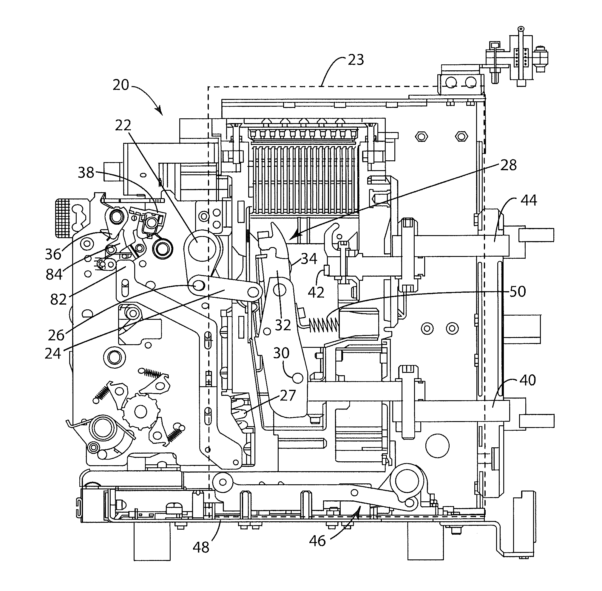
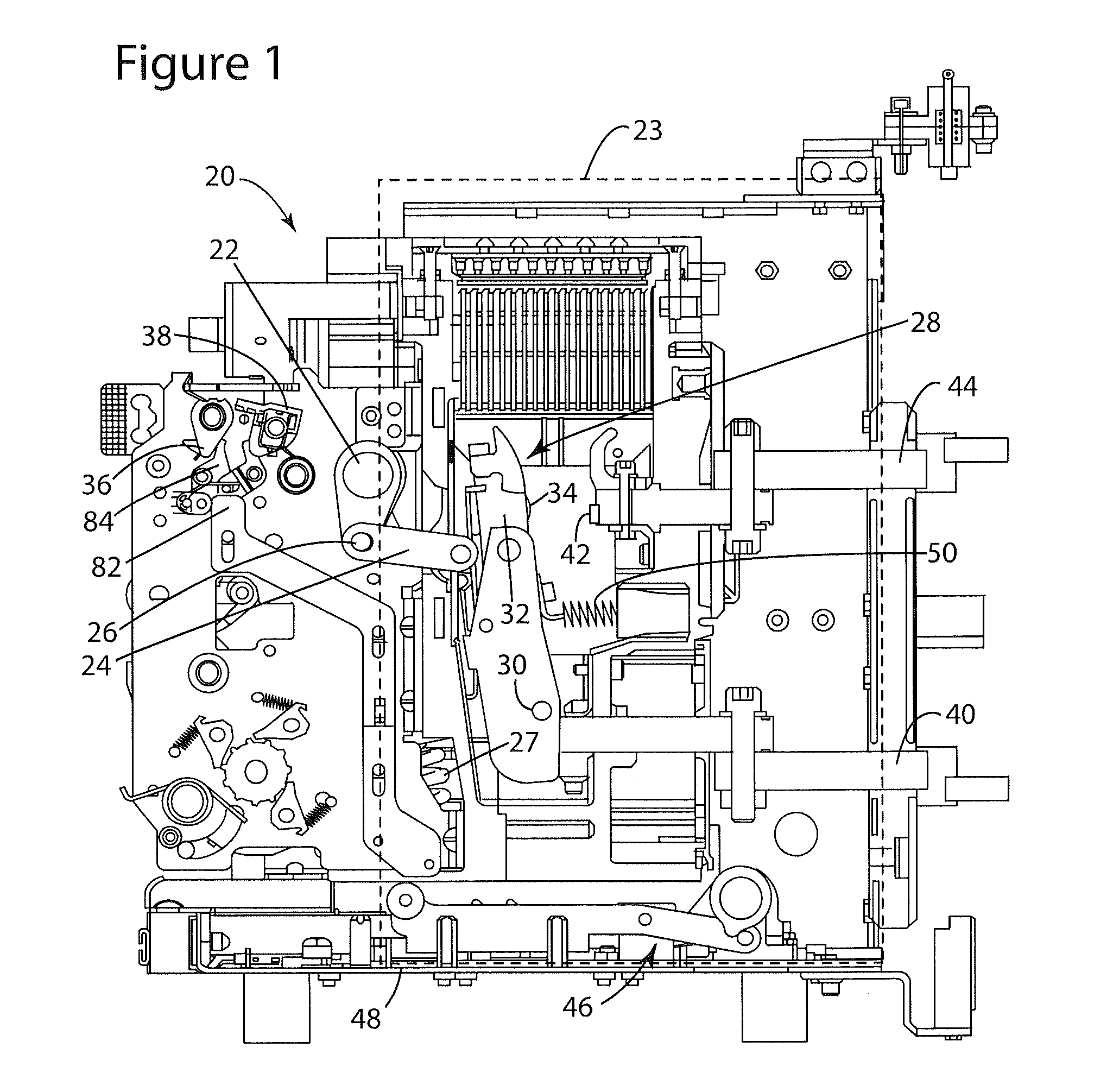
[0019]FIG. 1 illustrates a circuit breaker 20 in the open position. The circuit breaker 20 includes a main mechanism (not shown) arranged within a housing 23. The circuit breaker 20 further includes a racking cassette base 48 disposed on one end of the housing 23. The main mechanism is coupled to a lay shaft assembly 22 that rotates in response to the main mechanism being moved between an on and off position. The lay shaft assembly is coupled to a contact arm coupler 24 through a pin 26. The contact arm coupler 24 as illustrated in FIG. 1 is in a open position and will transfer energy from the main mechanism compression springs (closing springs) 27 that is necessary to close a contact arm assembly 28. The contact arm assembly 28 is mounted in the circuit breaker 20 to pivot about a pin 30 to move between a closed and open position.

[0020]It should be appreciated that the contact arm assembly 28 is illustrated in the exemplary embodiment as a single component. However, the contact arm...


PUM


Abstract

A circuit breaker and mechanism are provided for opening circuit breaker contact arms when the circuit breaker is moved between an installed and a withdrawn position in a drawout installation. The circuit breaker has a cross shaft coupled to a first linkage that rotates in response to the circuit breaker being moved. A second linkage translates in response to said first linkage rotating. A cam surface is operably coupled between the cross shaft and the first linkage. An opening latch shaft is coupled between the second linkage and a contact arm assembly such that the opening latch shaft moves the contact arm assembly from a closed position to an open position in response to the translation of the second linkage.

Description

BACKGROUND OF THE INVENTION[0001]The subject matter disclosed herein relates to a mechanism for a circuit breaker. In particular, the subject matter disclosed herein relates to a mechanism coupled to the circuit breaker that opens a contact arm structure and discharges the stored energy the mechanism springs prior to the circuit breaker being installed or removed from service.[0002]Air circuit breakers are commonly used in electrical distribution systems. A typical air circuit breaker comprises an assembly of components for connecting an electrical power source to a consumer of electrical power called a load. The electric circuit the circuit breaker is connected to is referred to herein as the protected electric circuit. The components are referred to as a main contact assembly. In this assembly, a main contact is typically either opened, interrupting a path for power to travel from the source to the load, or closed, providing a path for power to travel from the source to the load. ...

Claims


Application Information

Patent Timeline
Patent Type & Authority Patents(United States)
IPC IPC(8): H01H9/20H01H9/24H01H33/42
CPCH01H71/126H01H3/42
Inventor PAI, ARVINDBAVIKAR, KAPIL VINODRAOSAPURAM, SUDHAKARSISSON, GLEN CHARLES
Owner ABB SPA
Features
  • R&D
  • Intellectual Property
  • Life Sciences
  • Materials
  • Tech Scout
  • Unparalleled Data Quality
  • Higher Quality Content
  • 60% Fewer Hallucinations
Learn More