Method for determining relative motion using accelerometer data

a technology of accelerometer and relative motion, applied in the direction of vehicle position/course/altitude control, using reradiation, instruments, etc., can solve the problems of relative motion, deformation of the hull structure of the ship, and introduction of errors into the targeting information provided to the weapons system

Inactive Publication Date: 2013-09-03
LOCKHEED MARTIN CORP
View PDF12 Cites 6 Cited by
  • Summary
  • Abstract
  • Description
  • Claims
  • Application Information

AI Technical Summary

Problems solved by technology

Ship hull structures deform during at-sea operations due to vibration and wave interaction.
Such deformations result in relative motion between combat system elements such as radar systems, inertial navigation system (INS) sensors, and weapons systems.
Since these combat system elements are often located on different parts of the ship, relative motion between them can introduce error into the targeting information provided to the weapons systems.
Current Aegis combat systems do not compensate for this relative motion because the errors are deemed to be tolerable.
One problem with the Wernli system is that it requires the use of gyroscopes to measure rotational speeds.
Such gyroscopes are expensive and require complex isolation systems to meet Navy shock requirements, resulting in substantial acquisition and maintenance costs.

Method used


Image

  • Method for determining relative motion using accelerometer data
  • Method for determining relative motion using accelerometer data
  • Method for determining relative motion using accelerometer data

Examples


Embodiment Construction

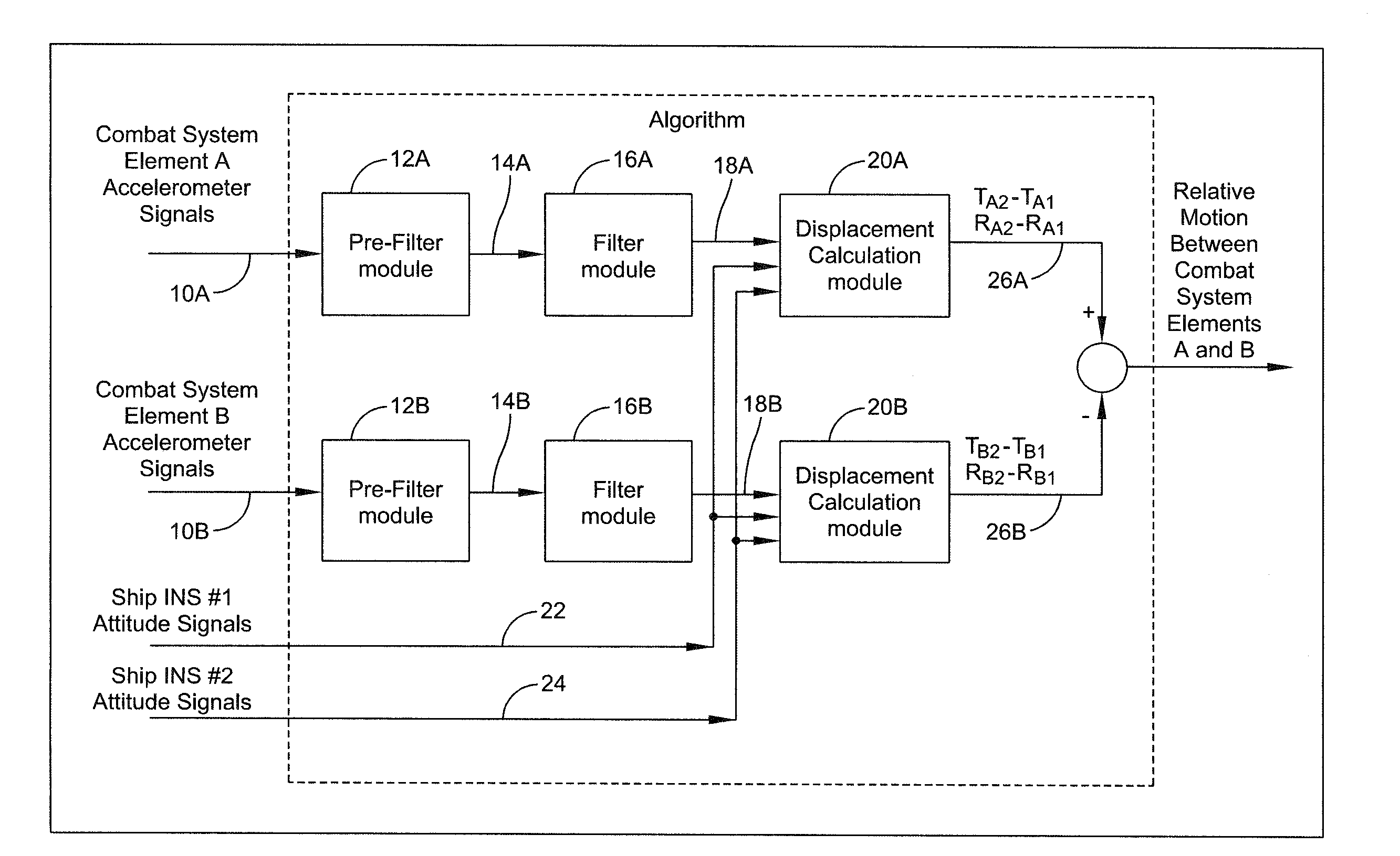
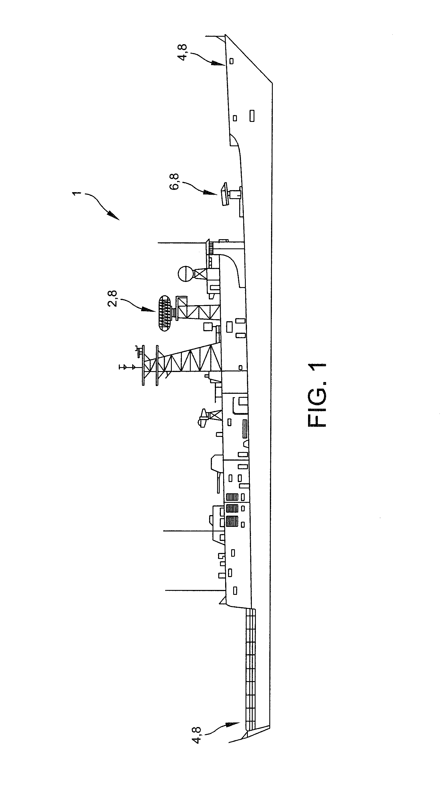
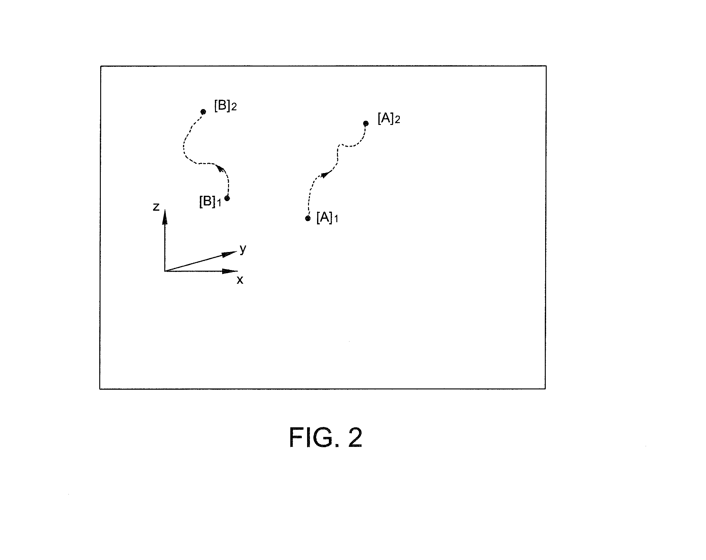
[0018]The invention is a system and method for determining relative motion between combat system elements positioned on a naval vessel 1, such as that illustrated in FIG. 1. The combat system elements may comprise radar systems 2, forward and aft inertial navigation system (INS) sensors 4, and weapons systems 6. “Relative motion” is described in relation to FIG. 2, in which a pair of combat system elements are labeled “A” and “B.” These elements can be any of the aforementioned components (radar, INS sensors, weaponry, etc.) The translational and rotational positions of combat system elements A and B at time t1 may be designated [A]1 and [B]1, while the translational and rotational positions of those same elements at time T2 may be designated [A]2 and [B]2. The positions may be further defined as follows:

[A]1=[TA1,RA1], where:

TA1=[tax1,tay1,taz1] (Translational position)

RA1=[rax1,ray1,raz1] (Rotational position)

[0019]Thus defined, the relative motion between combat system elements A...


PUM


Abstract

A method is disclosed for determining relative motion between equipment systems positioned on a structure that is subject to deformation due to vibrations, using accelerometers. Relative motion between equipment systems can introduce error into the targeting information provided to a system such as a weapons system, and thus the method facilitates compensation for such relative motion. A method is disclosed in which the raw accelerometer signals are filtered, then combined with attitude signals in a displacement calculation module (DCM). Within the DCM, the signals are manipulated to calculate, for each equipment system, the translational and rotational displacements due to hull modal vibration and the translational and rotational displacements due to force vibration. The sum of these values represent the movement of each of the affected equipment systems. Relative motion between systems is calculated as the difference between the calculated movement values.

Description

CROSS-REFERENCE TO RELATED APPLICATION[0001]This application is a divisional of U.S. patent application Ser. No. 11 / 869,283, filed Oct. 9, 2007 now U.S. Pat. No. 8,296,053, issued on Jun. 7, 2012 by Edward M. Brennan et al., titled “System and Method for Determining Relative Motion Between Ship Combat System Elements”, the entirety of which application is incorporated herein by reference.GOVERNMENT LICENSE RIGHTS[0002]This invention was made with Government support under contract number N00024-03-C-6110 awarded by the Department of the Navy. The Government has certain rights in this invention.FIELD OF THE INVENTION[0003]The invention relates to systems and methods for determining relative motion between bodies, and more particularly to systems and methods for compensating for relative motion between ship combat system elements.BACKGROUND OF THE INVENTION[0004]Ship hull structures deform during at-sea operations due to vibration and wave interaction. Such deformations result in relat...

Claims


Application Information

Patent Timeline
Patent Type & Authority Patents(United States)
IPC IPC(8): G05D1/02B63G1/00G01S13/00F41G7/00G01P15/00
CPCF42B15/01
Inventor BRENNAN, EDWARD M.JANNETTI, CARL V.STETSON, JOHN B.
Owner LOCKHEED MARTIN CORP
Why Eureka
Try Eureka