Quick-change wear sleeve for a high-pressure fluid conduit

a technology of fluid conduits and fast-change, which is applied in the direction of hose connections, couplings, transportation and packaging, etc., can solve the problems of flow convergence equipment, particularly severe wash problems, and the wear of the conduit through which fluids are pumped

Active Publication Date: 2013-09-10
OIL STATES ENERGY SERVICES +1
View PDF28 Cites 51 Cited by
  • Summary
  • Abstract
  • Description
  • Claims
  • Application Information

AI Technical Summary

Problems solved by technology

The conduits through which those fluids are pumped are therefore subject to wear due to erosion induced by the abrasive particles.
The problem of wash is particularly severe in fluid conduits where turbulent flow occurs.
Consequently, flow convergence equipment such as “frac heads”, “flow tees” and valves are generally most subject to wash.
While each of these inventions has merit, refurbishing them requires time and skill.

Method used


Image

  • Quick-change wear sleeve for a high-pressure fluid conduit
  • Quick-change wear sleeve for a high-pressure fluid conduit
  • Quick-change wear sleeve for a high-pressure fluid conduit

Examples


Embodiment Construction

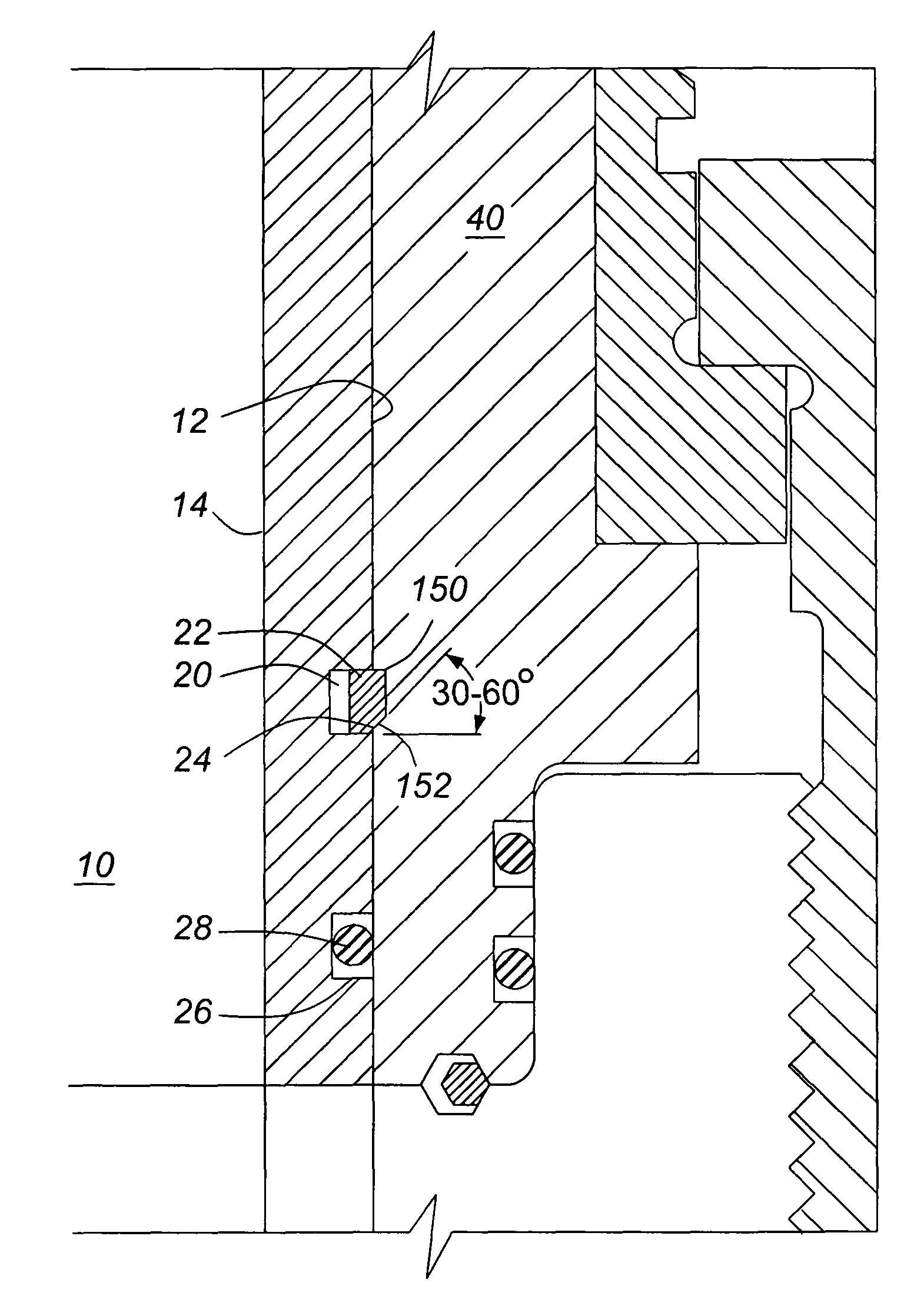
[0023]The invention provides a quick-change wear sleeve used to line, or partially line, fluid conduits through which high-pressure abrasive fluids are pumped. The quick-change wear sleeve is secured in the fluid conduit by a retainer ring. The retainer ring is received in a peripheral groove in an outer wall of the quick-change wear sleeve and in a complementary groove in an inner wall of the fluid conduit. The quick-change wear sleeve is readily removed from the fluid conduit using a sleeve puller, or the like. A replacement quick-change wear sleeve is readily installed in the fluid conduit using a ring compressor, or the like. A fluid conduit equipped with a quick-change wear sleeve in accordance with the invention can therefore be quickly and easily refurbished.

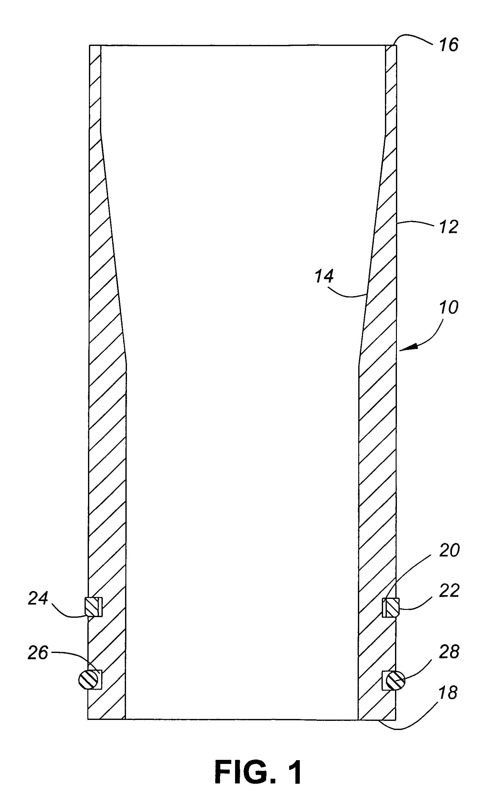
[0024]FIG. 1 is a schematic cross sectional diagram of an embodiment of a quick-change wear sleeve 10 in accordance with the invention. As shown in FIG. 1, the quick-change wear sleeve 10 is an elongated hollow cylinder o...


PUM


Abstract

A quick-change wear sleeve for a high pressure fluid conduit is retained in a fluid passage of the fluid conduit by a resilient retainer ring received in complementary grooves in an outer surface of the quick-change wear sleeve and an inner surface of the fluid passage.

Description

CROSS-REFERENCE TO RELATED APPLICATIONS[0001]This is the first application filed for the present invention.MICROFICHE APPENDIX[0002]Not Applicable.TECHNICAL FIELD[0003]The present invention relates generally to high-pressure fluid conduits for abrasive fluids and, in particular, to a quick-change wear sleeve for prolonging a service life of such fluid conduits.BACKGROUND OF THE INVENTION[0004]Most oil and gas wells require some form of stimulation treatment either during completion or re-completion in order to stimulate production from the well. Many well stimulation treatments require that well stimulation fluids be pumped at high pressure and at high rates into the well. Those well stimulation fluids are frequently laden with abrasive proppants such as sharp sand, bauxite or ceramic particles. The conduits through which those fluids are pumped are therefore subject to wear due to erosion induced by the abrasive particles. That wear is commonly referred to in the field as “wash”, a...

Claims


Application Information

Patent Timeline
Patent Type & Authority Patents(United States)
IPC IPC(8): F16L7/00
CPCF16L37/088F16L57/06Y10T137/7036Y10T137/598
Inventor MCGUIRE, BOB
Owner OIL STATES ENERGY SERVICES
Why Eureka
Try Eureka