Airbag device

a technology for airbags and occupants, which is applied in the direction of pedestrian/occupant safety arrangements, vehicular safety arrangments, vehicle components, etc., can solve the problems of delayed sealing of the lower chamber by the closure and lower inner pressure of the lower chamber

Active Publication Date: 2013-09-10
ASHIMORI INDS
View PDF22 Cites 33 Cited by
  • Summary
  • Abstract
  • Description
  • Claims
  • Application Information

AI Technical Summary

Benefits of technology

[0007]The present invention has been made in view of such conventional problems and an object thereof is to: start the closing movement of at least one of two or more air chambers partitioned in an airbag at an early stage; tightly close an inflated air chamber at an early stage; and keep the inflated state for a longer time through the use of a simple configuration of not increasing the number of parts in an airbag device.
[0009]The present invention makes it possible to: start the closing movement of at least one of two or more air chambers partitioned in an airbag at an early stage; tightly close an inflated air chamber at an early stage; and keep the inflated state for a long time through the use of a simple configuration of not increasing the number of parts in an airbag device.

Problems solved by technology

As a result, undesirably, the start of the closing operation of the lower chamber outlet port and the sealing of the lower chamber by the closure may be delayed and the inner pressure of the lower chamber may lower by then.
Consequently, the lower chamber outlet port, although how it closes is not obvious, starts to close gradually from a cylindrically expanded state after an occupant hits the lower chamber, hence it takes time until it is closed, and the sealing of the inflated lower chamber and the transfer to a state of being capable of maintaining the inner pressure may be delayed undesirably.

Method used


Image

  • Airbag device
  • Airbag device
  • Airbag device

Examples


Embodiment Construction

[0018]An embodiment of an airbag device according to the present invention will be explained in reference to drawings.

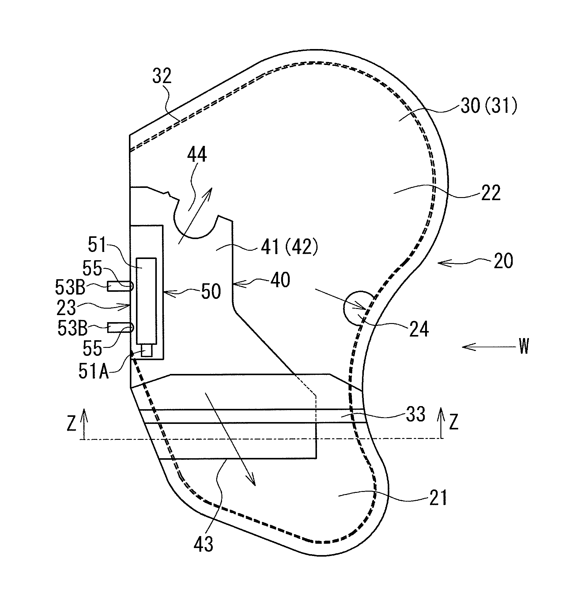
[0019]An airbag device according to the present embodiment is a device for protecting an occupant or the like seated in an automobile, for example, through the use of an inflated airbag and the following explanations will be made on the basis of a side airbag device for protecting an occupant from a side by inflating and deploying an airbag from a seat between a vehicle inner sidewall and the occupant.

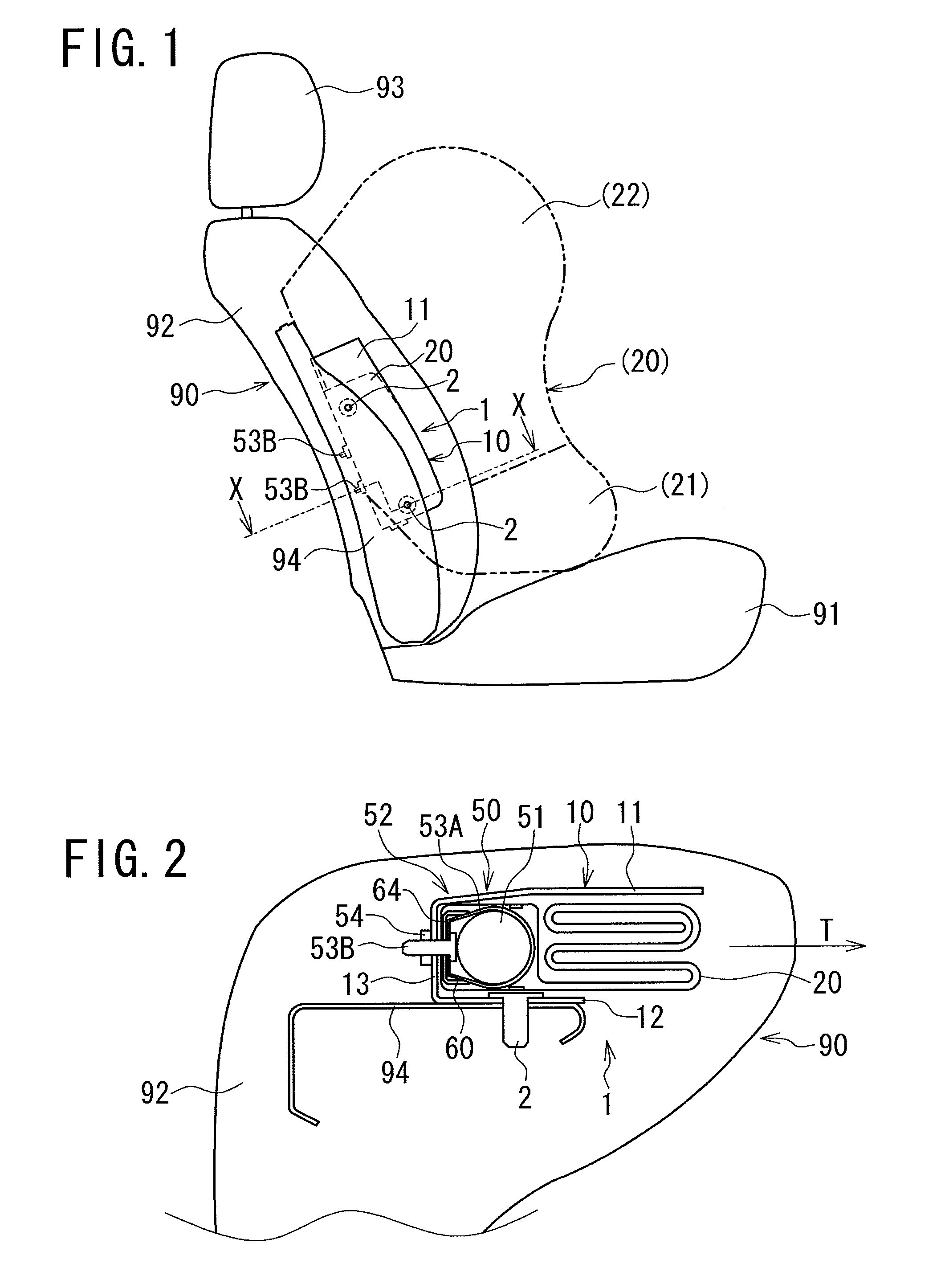
[0020]FIG. 1: is a side view schematically showing a substantial part of an airbag device according to the present embodiment in a state of being mounted on a vehicle; and perspectively shows the inside of a seat 90 viewed from the vehicle lateral direction. Furthermore, in the figure, the back side of the sheet represents the side of a vehicle inner sidewall such as a door, the front side of the sheet represents the occupant side (vehicle inner side), the right-hand si...


PUM


Abstract

Closing movement of at least one of two or more air chambers is started at an early stage, and an inflated air chamber is tightly closed and maintained in an inflated state for a long time. Inside of an airbag is partitioned into air chambers, with a partitioning cloth, and a diffuser that stores a gas generator is disposed in the air chambers, through the partitioning cloth. Gas from a gas generator is rectified by the diffuser, and is supplied from outlet parts, into the air chambers, thereby inflating and deploying the air chambers. An occupant side base cloth, a semi-perimeter portion around the lower outlet part, is connected to a back-side base cloth of the airbag, and in accordance with an inflation of the lower air chamber, a tension is imposed on the occupant side base cloth from the back-side base cloth, thereby elongating the lower air chamber. This causes the base cloths to come close to each other and gradually narrow the opening width, thereby enabling the base cloths to closely stick to each other so as to close the opening of the lower outlet part.

Description

CROSS REFERENCE TO RELATED APPLICATIONS[0001]This application is a National Stage of International Application No. PCT / JP2010 / 050099 filed on Jan. 7, 2010, which claims priority from Japanese Patent Application No. 2009-031036, filed on Feb. 13, 2009, the contents of all of which are incorporated herein by reference in their entirety.TECHNICAL FIELD[0002]The present invention relates to an airbag device that is mounted on a vehicle such as an automobile, in particular to an airbag device that has a diffuser for storing a gas generator in the expansible and deployable airbag partitioned into two or more air chambers, and rectifies gases generated through the diffuser and then supplies them to the respective air chambers.BACKGROUND ART[0003]In order to protect an occupant at the time of vehicle collision or emergency, there is widely used a side airbag device to protect the occupant from a side with air chambers formed in an airbag for mainly protecting the chest, the abdomen, and the...

Claims


Application Information

Patent Timeline
Patent Type & Authority Patents(United States)
IPC IPC(8): B60R21/233B60R21/2346B60R21/231B60R21/207B60R21/20B60R21/217B60R21/239
CPCB60R21/207B60R21/23138B60R21/233B60R21/2171B60R2021/2395B60R2021/161B60R2021/23146B60R2021/23324B60R21/2342
Inventor KOBAYSHI, HIROSHIYAMAUCHI, KEITAIMAI, KATSUNORI
Owner ASHIMORI INDS
Why Eureka
Try Eureka