Cutting mechanism for drawn wire at sprue of injection mold

A technology of injection mold and cutting mechanism, which is applied in the field of plastic molds and can solve problems such as defects on the product surface, affecting the appearance of the product, and affecting the automatic ejection of plastic parts from the mold, etc.

Active Publication Date: 2012-11-21
ZHEJIANG KAIHUA MOLDS
View PDF4 Cites 10 Cited by
  • Summary
  • Abstract
  • Description
  • Claims
  • Application Information

AI Technical Summary

Problems solved by technology

[0002] After the injection mold is opened, the molded plastic parts will leave the cavity along with the core, and then demould, but when some plastic parts (such as polystyrene) leave the cavity, the nozzle of the injection machine will There is often a drawing between the plastic part and the plastic part. If it cannot be cut in time, it will not only affect the automatic ejection of the plastic part from the mold, but also the nozzle of the injection machine will inject the cooled drawing and the hot melted plastic into the cavity during the next injection. As a result, the surface of the manufactured product has defects and blemishes, which affect the appearance of the product; and when the wire drawing is elongated, it is still not cut, and the elongated cooling and hardening wire drawing will hang on the parting surface of the cavity or core , After the mold is closed, the cavity and the core are sandwiched by the drawing wire, which causes the mold to not close tightly, and it is easy to crush the parting surface, which affects the precision and service life of the mold.

Method used


Image

  • Cutting mechanism for drawn wire at sprue of injection mold
  • Cutting mechanism for drawn wire at sprue of injection mold
  • Cutting mechanism for drawn wire at sprue of injection mold

Examples


Embodiment Construction

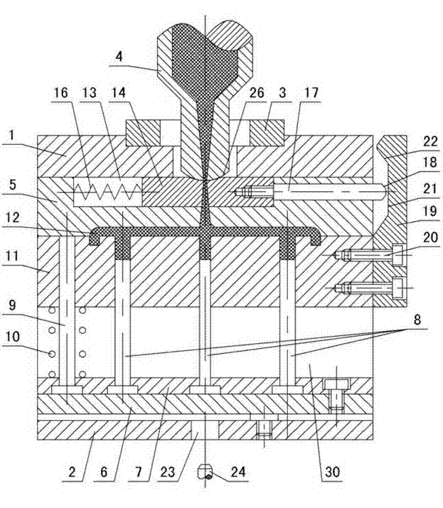
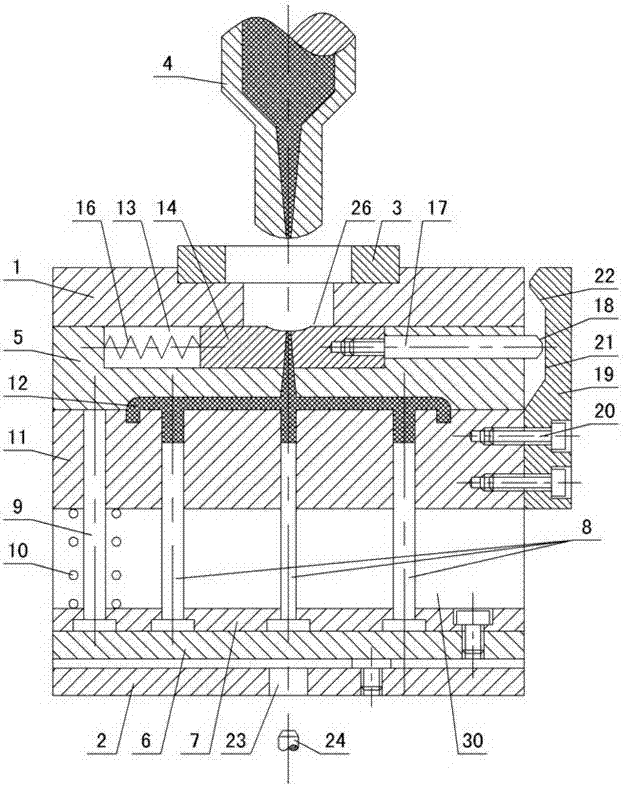
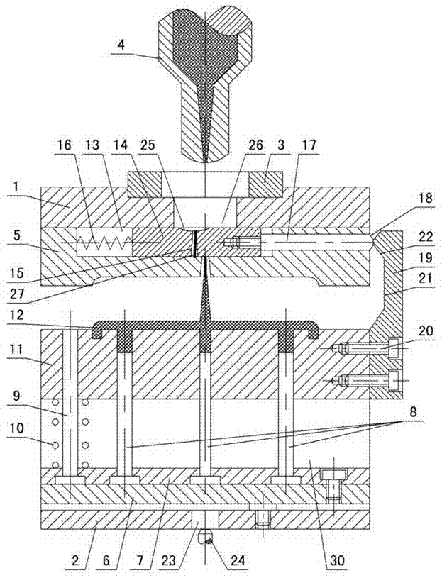
[0011] The invention relates to a wire drawing and cutting mechanism for the gate of an injection mold, such as figure 1 — Figure 4 As shown, it includes the upper doubler plate 1 and the lower doubler plate 2, and the positioning ring 3 is installed on the upper doubler plate 1, and the nozzle 4 of the injection machine is installed in the positioning ring, the upper doubler plate 1 is connected with the cavity 5, and the lower doubler plate 2 There are mold feet 30, and there are lower ejector plate 6 and upper ejector plate 7 between the mold feet, and a through hole 23 is formed in the center of the lower double plate 2, and the push rod 24 of the injection molding machine passes through the through hole 23 and contacts the lower ejector plate 6, Fix the thimble 8 and the reset rod 9 in the upper thimble plate, the reset rod passes through the core 11, there is a plastic part 12 between the core 11 and the cavity 5, and it is characterized in that a groove 13 is formed in...


PUM


Abstract

The invention discloses a cutting mechanism for a drawn wire at a sprue of an injection mold. The cutting mechanism comprises an upper sheath and a lower sheath. A nozzle of an injector is arranged in a positioning ring which is arranged on the upper sheath. The lower part of the upper sheath is connected with a mold cavity. An upper thimble plate and a lower thimble plate are arranged between support blocks on the lower sheath. A through hole is formed in the lower sheath. A pushrod of the injector penetrates through the through hole, and contacts with the lower thimble plate. Thimbles and a return pin are fixedly arranged in the upper thimble plate. The return pin penetrates through a mold core. A plastic part is arranged between the mold core and the mold cavity. The cutting mechanism is characterized in that a cutting groove is formed in the mold cavity; an injection hole is formed in a sprue cutting block in the cutting groove, and is aligned with the nozzle of the injector and a runner hole of the mold cavity; one side of the sprue cutting block is connected with a compression spring which contacts with the inner wall of the mold cavity, and a pushrod is fixedly arranged on the other side of the sprue cutting block; an outer inclined surface is arranged on the head part of the pushrod; a pressure block is arranged on the outer wall of the side, which is the same as that of the pushrod, on the mold core, and the pressure block is fixed together with the mold core through screws; a plane and an inner inclined plane are arranged on the inner wall of the pressure block; and the inner inclined plane contacts with the outer inclined plane of the head part of the pushrod.

Description

technical field [0001] The invention relates to an injection mold, in particular to a wire drawing and cutting mechanism for a gate of an injection mold, and belongs to the field of plastic molds. Background technique [0002] After the injection mold is opened, the molded plastic parts will leave the cavity along with the core, and then demould, but when some plastic parts (such as polystyrene) leave the cavity, the nozzle of the injection machine will There is often a drawing between the plastic part and the plastic part. If it cannot be cut in time, it will not only affect the automatic ejection of the plastic part from the mold, but also the nozzle of the injection machine will inject the cooled drawing and the hot melted plastic into the cavity during the next injection. As a result, the surface of the manufactured product has defects and blemishes, which affect the appearance of the product; and when the wire drawing is elongated, it is still not cut, and the elongated...

Claims


Application Information

Patent Timeline
Patent Type & Authority Applications(China)
IPC IPC(8): B29C45/38
Inventor 李过
Owner ZHEJIANG KAIHUA MOLDS
Why Eureka
Try Eureka