Setting tool

a technology of setting tool and magazine, which is applied in the direction of manufacturing tools, nailing tools, stapling tools, etc., can solve the problem of dirt entering the magazine more difficul

Active Publication Date: 2011-07-19
HILTI AG
View PDF4 Cites 10 Cited by
  • Summary
  • Abstract
  • Description
  • Claims
  • Application Information

AI Technical Summary

Benefits of technology

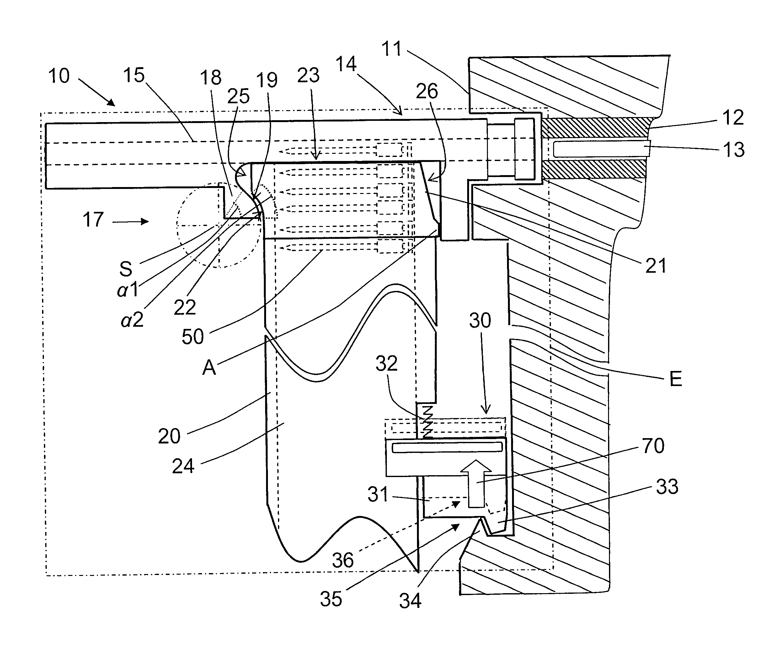
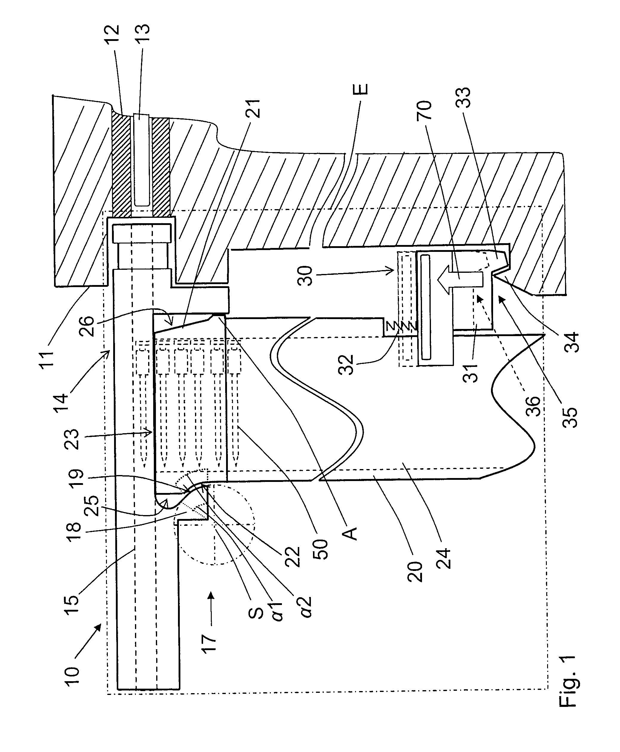
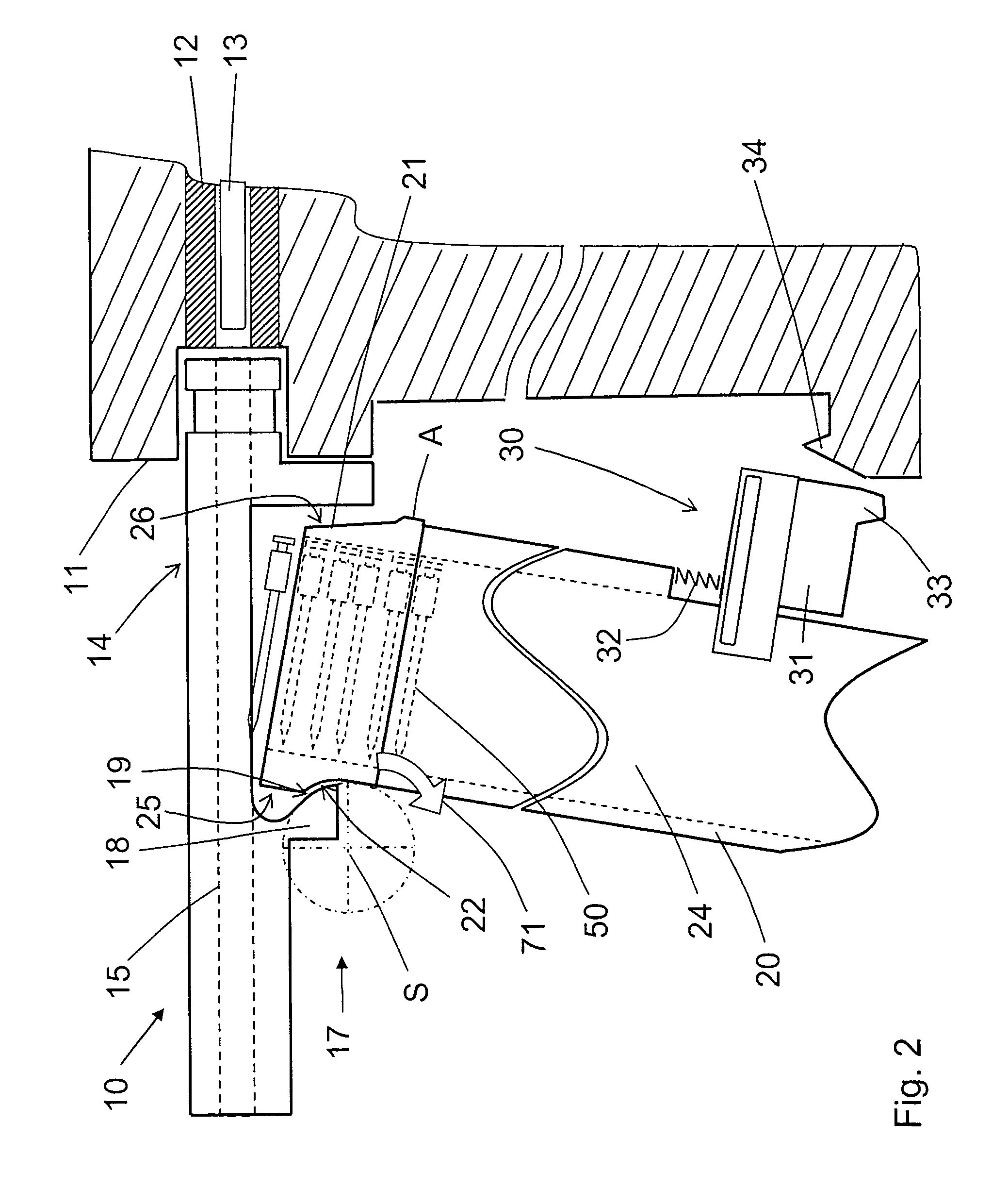
[0013]The novel features of the present invention permit to mount or to secure the magazine on the muzzle by a simple plug-in or push-in movement of both support means toward each other, without a need in any screw. On the other hand, in view of the position of the pivot axis of the hinge bearing, the magazine can be pivoted on the muzzle collision-free within a limited space. With a tight mounting of the magazine on the muzzle, penetration of dirt into the magazine becomes more difficult.
[0014]Advantageously, the first support means is formed as a curved support surface provided on the connection section of the magazine, and the second support means is formed as a complementary curved counter-support surface provided on the muzzle. The curved support surface and the curved counter-support surface are brought in engagement with each other to form a plug-in coupling. Preferably, the radius of the curved support surface and the radius of the curved counter-support surface are the same. Thereby, a simple positioning of both bearing sections over each other and, thus, of the magazine on the muzzle, and an easy pivoting during the pivotal process become possible. Further, the support and counter-support surfaces can be formed relatively large. Thereby, the impact loads and surface pressure are reduced, preventing separation of the support surfaces.
[0015]According to a further advantageous embodiment of the invention, the support surface of the hinge bearing is concave, and the counter-support surface is convex. Thereby, upon mounting of the magazine on the muzzle, pivoting the magazine toward the housing is possible.
[0017]It is further advantageous when there is provided further connection means between the magazine and the housing and which is formed as snap connection means having a slide displaceable along a longitudinal extent of the magazine (and provided on a one of portions of the magazine and the housing) and carrying a snap member that cooperates with a counter-snap member (provided on another of portions of the magazine and the housing). There is further provided at least one elastic element for biasing the slide. The slide biases, in its biased position, the magazine against the muzzle in the snap position of the magazine. The snap connection means permits attachment of the magazine to the housing in a simple manner in addition to the hinge bearing because the snap connection automatically snaps in when the magazine is pressed against the housing of the setting tool, whereby the magazine becomes connected with the setting tool housing. Simultaneously, with the magazine being pressed against the muzzle or the bolt guide, which is provided in the muzzle, a tight connection of the muzzle or the bolt guide on one hand, and the connection section of the magazine, on the other hand, is provided. The seam between the magazine and the muzzle is tightly closed.
[0018]It is further advantageous when the slide is provided on the magazine and is biased by the elastic element in a direction away from the connection section. The snap member is provided at an end of the slide remote from the connection section and adjacent to the housing, and the counter-snap member is provided on the housing. This provides for a simple two-hand operation during detachment of the magazines from the setting tool. The tool operator holds the setting tool in one hand and the magazine in another hand and simultaneously displaces the slide, opening the snap connection.

Problems solved by technology

With a tight mounting of the magazine on the muzzle, penetration of dirt into the magazine becomes more difficult.

Method used


Image

  • Setting tool
  • Setting tool
  • Setting tool

Examples


Embodiment Construction

[0024]FIGS. 1 through 3 show a muzzle region of a hand-held setting tool 10 according to the present invention. The setting tool 10 can be formed as an electrically or combustion-operated power tool and includes a setting mechanism located in the tool housing 11. The setting mechanism includes a drive member 13 that is formed as a setting piston and is displaceable in a guide 12. In FIGS. 1 through 3, the drive member 13 is shown in its initial position in which the drive member 13 is ready for a setting process.

[0025]The setting tool 10 is provided with a bolt guide 15 that is arranged in the muzzle 14 of the setting tool 10. The bolt guide 15 extends coaxially with the guide 12 for the drive member 13. The muzzle 14 is placeable with its free end, remote from the housing 11, against a workpiece. The bolt guide 15 serves for receiving and guiding fastening elements 50 (shown in FIG. 1) and for guiding a fastening element-driving end of the drive member 13. A fastening element 50, w...


PUM


Abstract

A setting tool for driving fastening elements in a constructional component, includes a muzzle (14), a bolt guide (15) located in the muzzle (14), a magazine (20) for fastening elements (50) and releasably mountable on the tool housing (11) and having a connection section (21) provided at an end of the magazine (20) adjacent to the muzzle (14) and with which the magazine (20) is secured to the muzzle (14), and a connection device for releasably mounting the magazine on the tool housing (11) and including a hinge bearing formed as a plug-in coupling and provided with a first support element arranged on the connection section (21) of the magazine (20) and a second support element arranged on the muzzle (14), with the hinge bearing (17) having a pivot axis (S) provided on a side of the magazine (20) remote from the housing (11), outside of the magazine (20) and outside of the muzzle (14) and extending at a right angle to a plane (E) defined by the bolt guide (15) and the magazine (20).

Description

BACKGROUND OF THE INVENTION[0001]1. Field of the Invention[0002]The present invention relates to a setting tool for driving fastening elements in a constructional component and including a housing, a guide located in the housing, a drive member displaceable in the guide, a muzzle, a bolt guide located in the muzzle, a magazine for fastening elements and releasably mountable on the housing and having a connection section provided at an end of the magazine adjacent to the muzzle and with which the magazine is secured to the muzzle, and connection means located between the muzzle and the magazine and including a hinge bearing provided with first support means arranged on the connection section of the magazine and second support means arranged on the muzzle.[0003]2. Description of the Prior Art[0004]The setting tools of the type described above can be driven with solid, gaseous, or liquid fuels, compressed air or electrical energy.[0005]In this setting tool, in which the drive member su...

Claims


Application Information

Patent Timeline
Patent Type & Authority Patents(United States)
IPC IPC(8): B25C1/08
CPCB25C5/16B25C1/005
Inventor DITTRICH, TILOFIELITZ, HARALDSCHNEIDER, ROLANDTILLE, DIERK
Owner HILTI AG
Why Eureka
Try Eureka