Robot end effector with cable management

a technology of end effectors and robots, applied in transportation and packaging, hoisting equipment, manufacturing tools, etc., can solve problems such as deterioration, bend, turn and/or twist of utility lines,

Active Publication Date: 2013-09-10
AMF AUTOMATION TECH
View PDF27 Cites 14 Cited by
  • Summary
  • Abstract
  • Description
  • Claims
  • Application Information

AI Technical Summary

Problems solved by technology

The turning, tilting, raising, stretching and lowering of the end effector with respect to the robot arm cause the utility lines to bend, turn and / or twist and to deteriorate over time, and they must be replaced and / or repaired.

Method used


Image

  • Robot end effector with cable management
  • Robot end effector with cable management
  • Robot end effector with cable management

Examples


Embodiment Construction

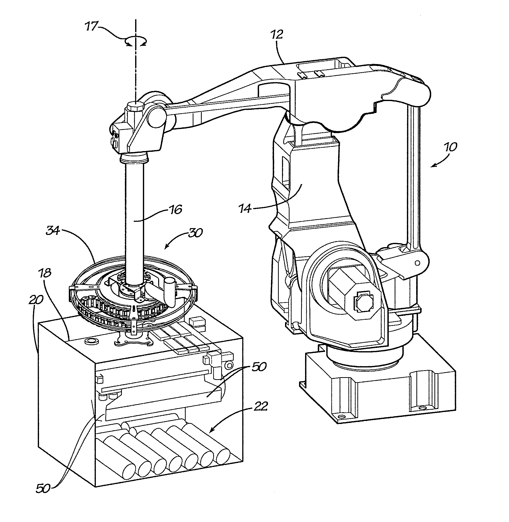
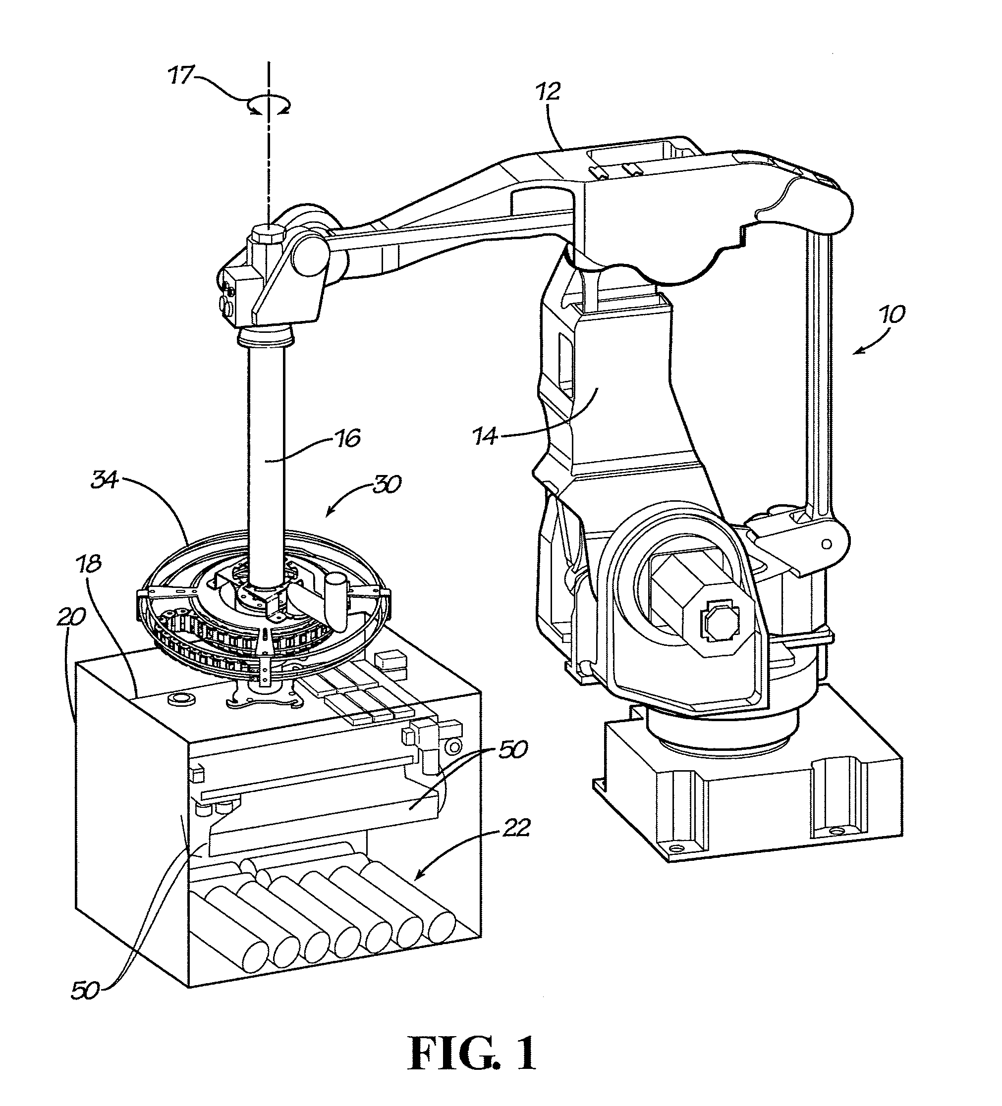
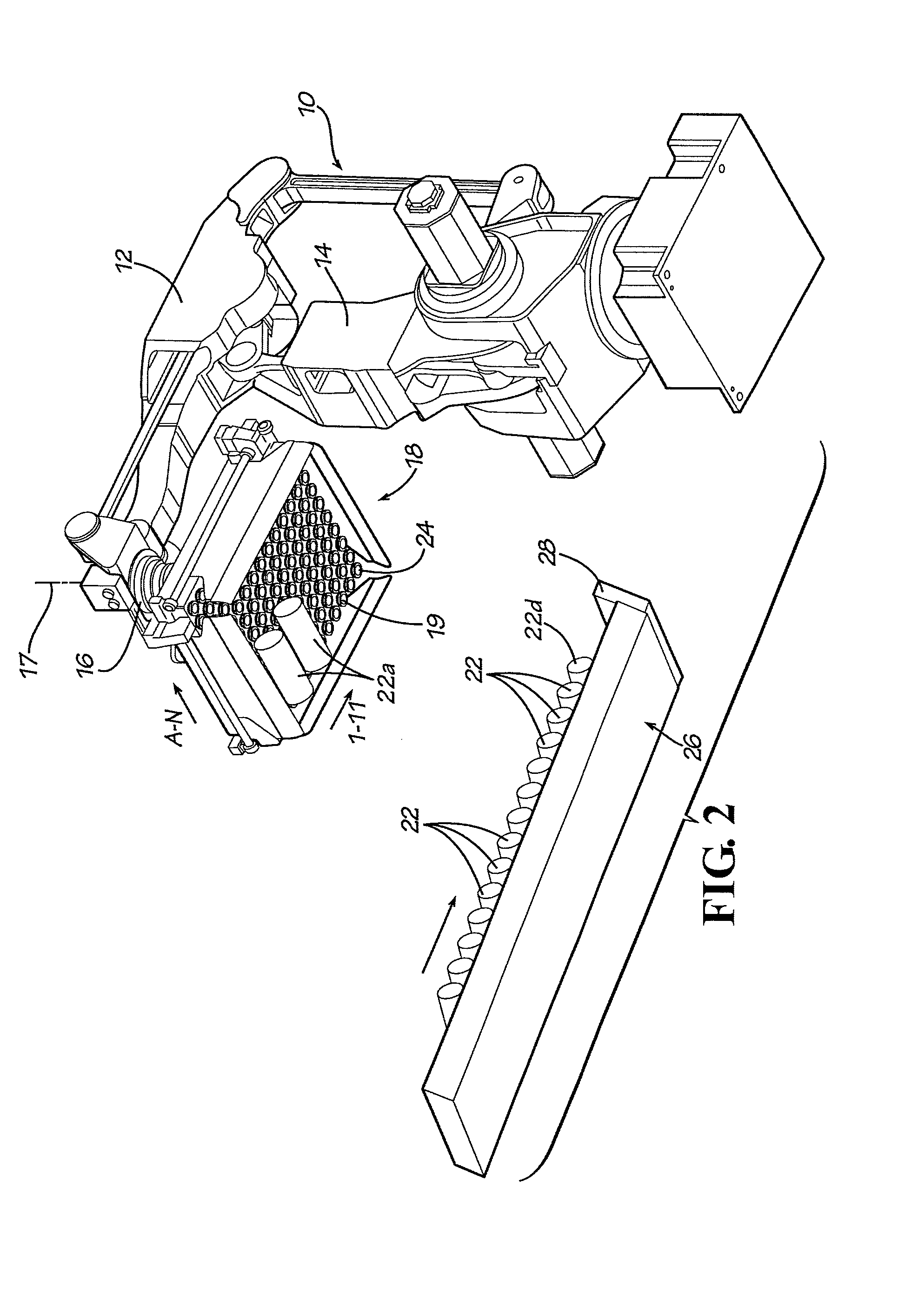
[0031]Referring now in more detail to the drawings, in which like numerals indicate like parts throughout the several views, FIGS. 1 and 2 illustrate a robot 10 of conventional articulating design, being pivotal about an upright axis, having a rocker arm 12 mounted on a rotary stanchion 14, and an articulating robot arm 16 mounted at its upper end to the distal end of the rocker arm. The end effector 18 is mounted to the distal end of the robot arm 16 and the movements of the end effector usually are controlled by a program entered in the robot's computer system. The robot arm and the rotary stanchion have parts therein (not shown) with the capacity to rotate, lift, lower, tilt and moved laterally the end effector, as is common in the art.

[0032]As shown in FIG. 1, the end effector 18 has been placed in alignment with the container 20 which is a packing container. The work products 22 have been released by the end effector 18 and have been deposited on the bottom wall of the containe...


PUM


Abstract

Cable manager 30 is positioned between the distal end of a robot arm 16 and the robot end effector 18. Elongated cable carrier 44 positioned in a circular cable track 34 extends in an arc about the axis of connection 17 between the robot arm and the end effector. One end 56 of the cable carrier moves with the robot arm and the other end 54 moves with the end effector. The cable carrier forms a U-shape 60 between its ends so that the movements of the ends of the cable carrier result in the U-shape accommodating the change in distance between the ends of the utility line and the cable carrier. Utility lines 62 are gathered in one or more cables that extend through the cable carrier to provide the end effector with the controls necessary for its operation.

Description

TECHNICAL FIELD[0001]This disclosure concerns a robotic packaging apparatus having a vacuum actuated end of arm effector for collecting work products of different shapes and sizes in different patterns for delivery to a receptacle, such as to a shipping container. More particularly, this disclosure concerns a cable management system for controlling and aligning the utility lines such as vacuum conduits, air lines, electrical and sensor cables, that extend between an articulated robot arm and the attached rotating and multi-axis moving vacuum head, known as an end of arm effector (hereinafter “end effector”). The cable management system reduces twisting, breaking, wear and the fatigue on the utility lines connected between the robotic arm and the end effector.BACKGROUND OF THE DISCLOSURE[0002]In robotic packaging operations, a producer might desire to ship work products in shipping containers of a standard shape and size. Robots might be used for performing the packing of the goods i...

Claims


Application Information

Patent Timeline
Patent Type & Authority Patents(United States)
IPC IPC(8): B66F19/00
CPCA21C15/00B25J19/0025B65G47/915B25J11/0045B25J15/0616Y10T74/20311B65G2201/0202
Inventor ROBINSON, DENNIS LEELOMERSON, JR., ROLAND
Owner AMF AUTOMATION TECH
Why Eureka
Try Eureka