
Retractable drill mounted dust collector

a dust collector and drill head technology, applied in the field of dust collection, can solve the problems of annoyance or obstructing the vision material often falling on the face or clothing of the drill user, and material is often sharp and/or hot, so as to prevent or reduce the damage to the work surface

Inactive Publication Date: 2013-09-10
EVERINGTON JR ERNEST
View PDF17 Cites 7 Cited by
  • Summary
  • Abstract
  • Description
  • Claims
  • Application Information

AI Technical Summary

Benefits of technology

The present invention is a device to collect dust released during drilling using an electric drill. The device has a forward ring, a collapsible cylindrical center portion, a rear ring, and wall. It also has drawstrings that can be extended or collapsed to allow the user to see the surface being drilled while collecting the dust. The device is designed to prevent damage or marring to the surface and to provide a clear view during drilling. The technical effects of this invention include improved safety, efficiency, and accuracy during drilling operations.

Problems solved by technology

Drilling operations are often performed in either a clean environment where dust control is important or even essential, or in a manner which allows material removed by the drill to fall towards the drill user thus annoying or obstructing the vision of the drill user.
In particular, when drilling overhead, material often falls onto a drill user's face or clothing.
Such material is often sharp and / or hot.
Unfortunately, the view of the working area is obstructed or distorted by having to look through the bowl, and the drill user may have difficulty guiding the drilling or cutting.
U.S. Pat. No. 6,053,674 for “Dust Collecting Assembly for Drilling Tools” is similar to the apparatus of the '820 application, additionally including a vacuum cleaner attachment, but the problems of the '820 application remain to at least some degree.
As in the case with the '820 application and the '674 patents, the presence of the solid cylinder obstructs or distorts the drill user's view of the work area.
Unfortunately, the apparatus of the '146 patent obstructs viewing the work to some extent.
Unfortunately, the device of the '123 patent also obstructs viewing the work to some extent.

Method used


Image

  • Retractable drill mounted dust collector
  • Retractable drill mounted dust collector
  • Retractable drill mounted dust collector

Examples


Embodiment Construction

[0022]The following description is of the best mode presently contemplated for carrying out the invention. This description is not to be taken in a limiting sense, but is made merely for the purpose of describing one or more preferred embodiments of the invention. The scope of the invention should be determined with reference to the claims.

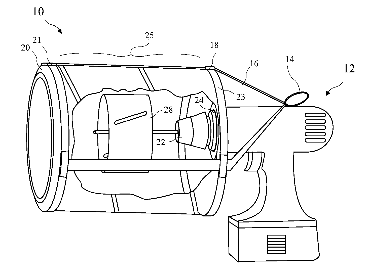
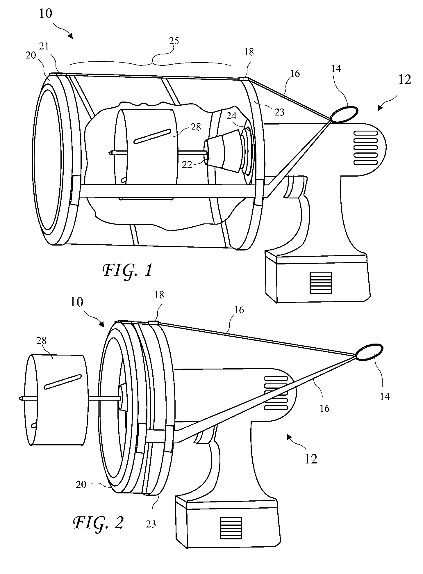
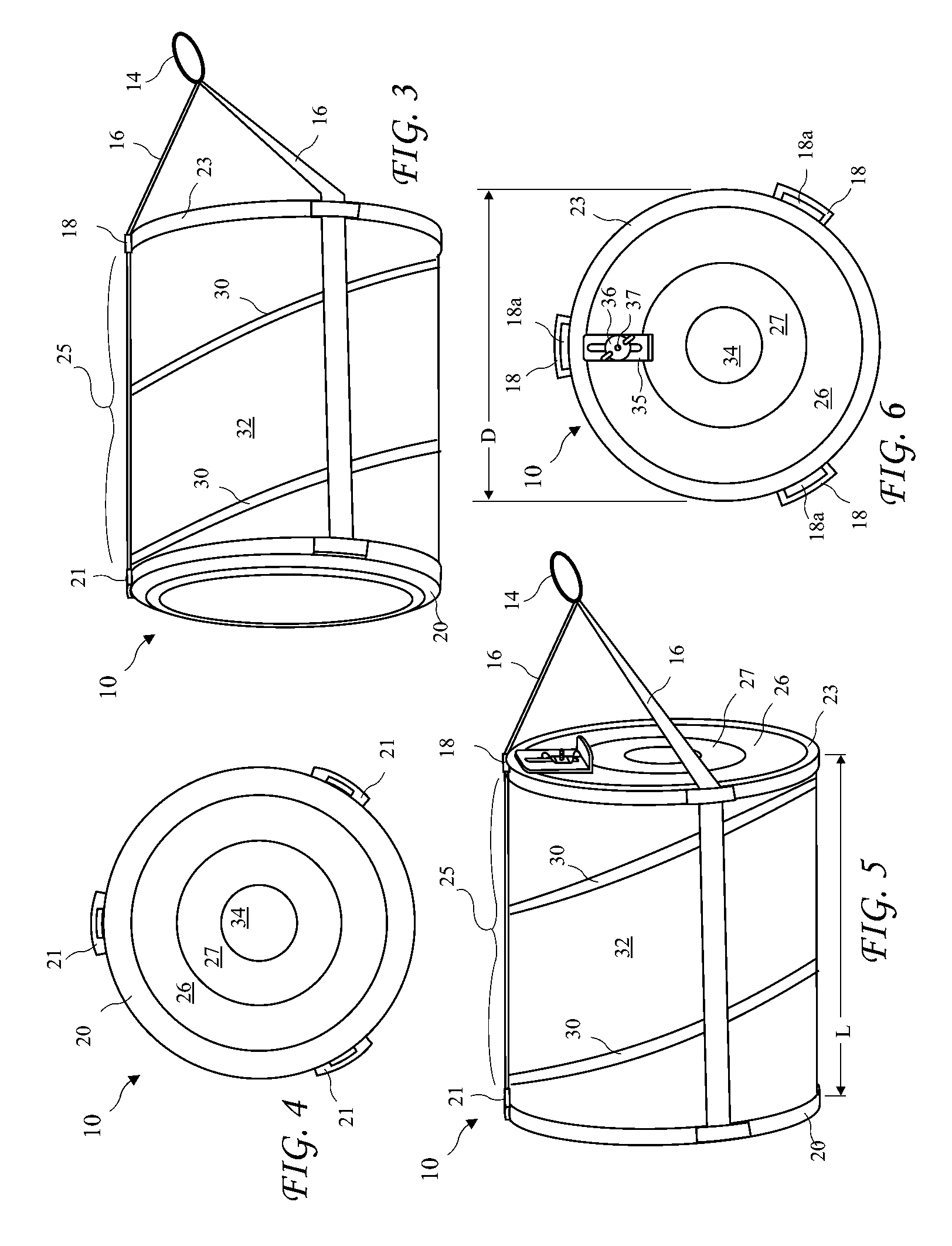
[0023]A side perspective view of a retractable drill mounted dust collector 10 according to the present invention mounted to an electric drill 12, with the retractable drill mounted dust collector 10 partially cut away to show a hole saw 28 attached to a rotating drill chuck 22 of the electric drill 12 is shown in FIG. 1, and a side perspective view of the dust collector 10 mounted to the electric drill 12 with the dust collector 10 retracted is shown in FIG. 2. The dust collector 10 includes a forward ring 20, a longitudinally collapsible cylindrical center portion 25, a rear ring 23, rigid wall 26, and pliable wall 27 attached to the rear ring 2...


PUM

PropertyMeasurementUnit
diameteraaaaaaaaaa
diameteraaaaaaaaaa
diameteraaaaaaaaaa

Abstract

A retractable dust containment device includes a forward ring, a collapsible cylindrical center portion, a stretchable rear cover, and draw strings. The forward ring is made from or covered by a plastic or soft material to prevent or reduce marring or damage to a work surface. The center portion includes a spring element pushing the forward ring away from the rear cover, and is enclosed by material to contain dust. The rear cover is a rubber like material and includes a window sized to allow a chuck and rotating drill elements to pass through and seat a non-rotating nose of the drill in the window. Draw strings pass through guides on the perimeter of the rear cover, attach to the forward ring, and are joined behind the rear cover, allowing the forward ring to be drawn to the rear to allow clear viewing on the work surface.

Description

BACKGROUND OF THE INVENTION[0001]The present invention relates to dust collecting and in particular to a retractable dust collector which attaches to a hand held drill.[0002]Drilling operations are often performed in either a clean environment where dust control is important or even essential, or in a manner which allows material removed by the drill to fall towards the drill user thus annoying or obstructing the vision of the drill user. In particular, when drilling overhead, material often falls onto a drill user's face or clothing. Such material is often sharp and / or hot.[0003]Known apparatus provides a partial solution to this problem. For Example, US Patent Application Serial No. 2004 / 0141820 for “Debris Catching Device for Abrasive and Cutting Tools” discloses a bowl held against an overhead surface, and a drill or hole saw operated inside the bowl from a drill below the bowl. Unfortunately, the view of the working area is obstructed or distorted by having to look through the ...

Claims


Application Information

Patent Timeline
Patent Type & Authority Patents(United States)
IPC IPC(8): B23B47/34
CPCB23Q11/0046Y02P70/171Y10T408/50Y10T409/304088
Inventor EVERINGTON, JR., ERNEST
Owner EVERINGTON JR ERNEST
Learn More