Power supply cord storage mechanism

a power supply cord and storage mechanism technology, applied in the direction of machine supports, coupling device connections, other domestic objects, etc., can solve the problems of power cords simply left in a jumble, power cords that cannot be secured, and cannot facilitate the maintenance or orderly wrapping of associated power cords, etc., to achieve simple, quick and convenient maintenance, simple, and convenient

Inactive Publication Date: 2013-09-10
FRENKIL LEONARD
View PDF39 Cites 13 Cited by
  • Summary
  • Abstract
  • Description
  • Claims
  • Application Information

AI Technical Summary

Benefits of technology

[0004]The disclosed implementations provide a simple, quick, and convenient means of managing the orderly use and storage of power cords of portable electric and electronic power supply units. It may be implemented in the initial manufacture and made a part of the power supply unit or it may be implemented retrospectively by being attached either releasably or permanently to the power supply unit body. The design assists in the maintenance of orderly control of the power cord(s) whether being extended partially or fully. For example, the recesses formed in the ends of the extensions or guides discussed herein allow capture of various sized power cords at any location along the flexible portion of the cord, so that if a user wants to shorten or lengthen the cord during use, the present implementations provide a quick, unique, and easy means of doing so.

Problems solved by technology

However, these and other wrapping methods fail to facilitate the orderly wrapping or maintenance of the associated power cords, nor do they provide for the securing of the power cord ends.
Invariably, the unsecured ends and the cords become loose and tangled or for lack of a readily usable storage solution, the power cords are simply left in a jumble to be untangled later.
This turns out to be an inefficient and mediocre solution to the problem at best and users then tend to ignore the tape or find it annoying and remove it.

Method used


Image

  • Power supply cord storage mechanism
  • Power supply cord storage mechanism
  • Power supply cord storage mechanism

Examples


Embodiment Construction

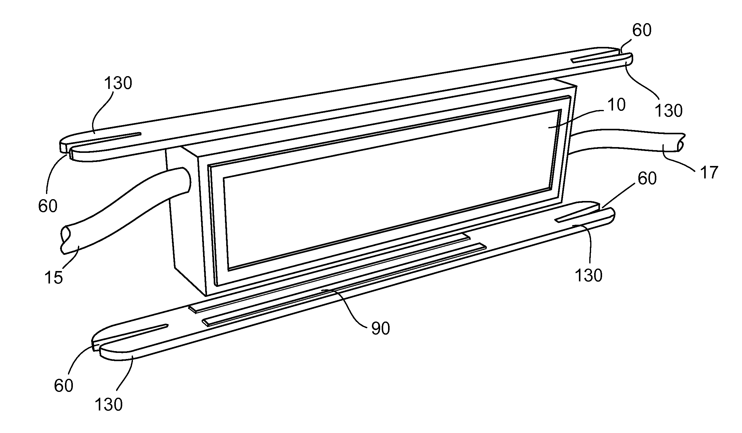
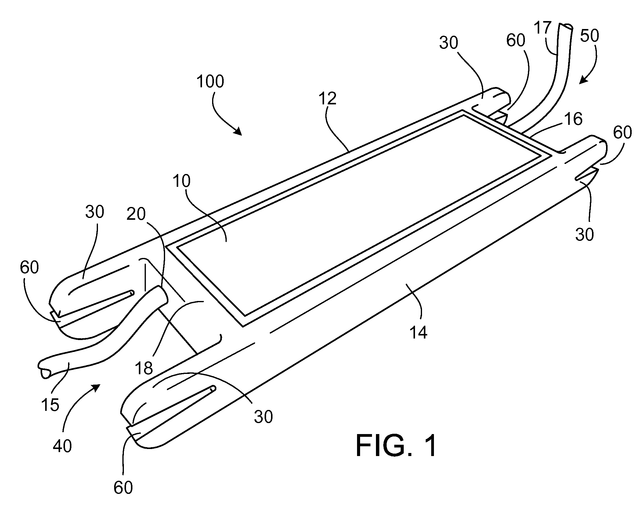
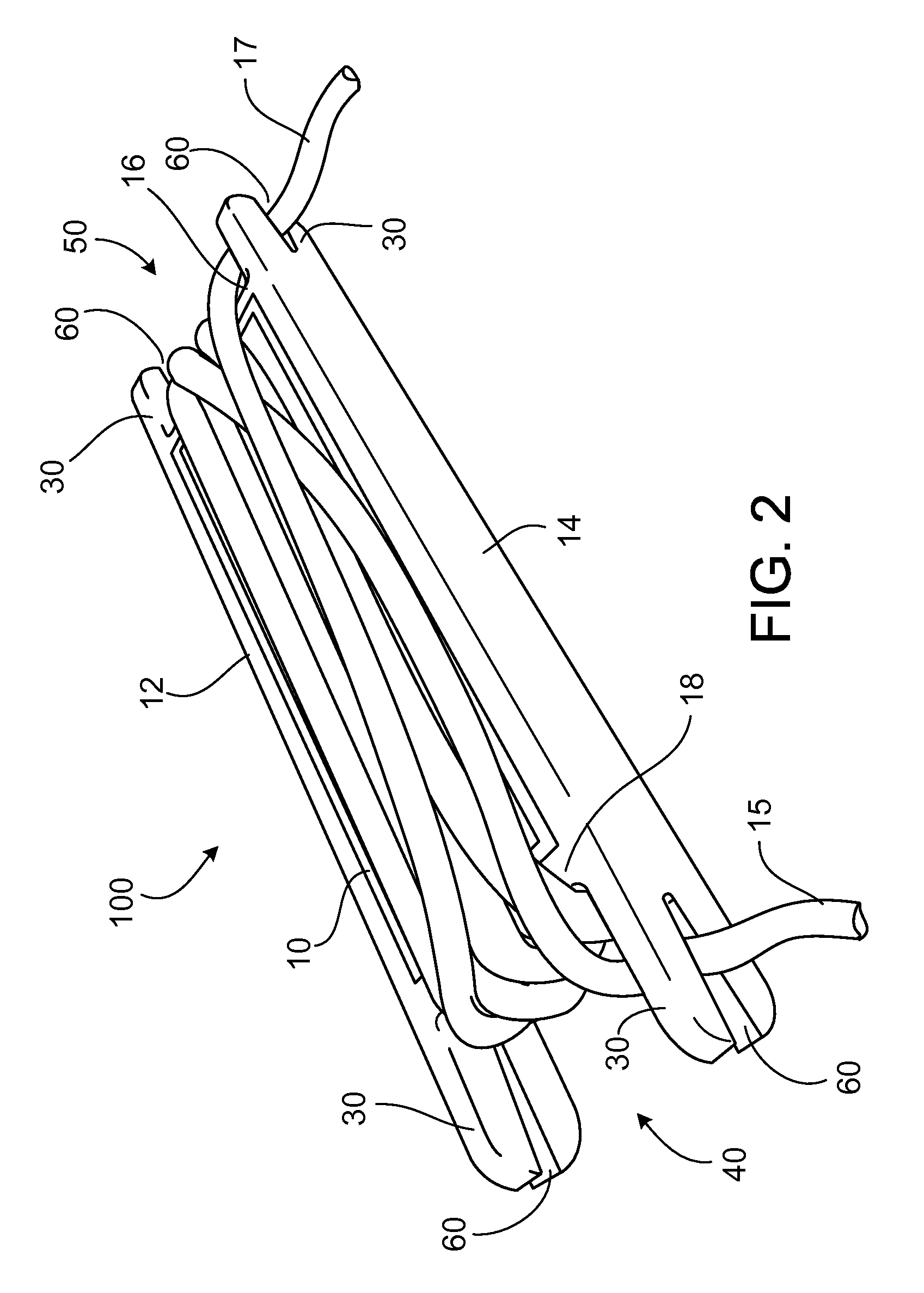
[0021]Referring to the accompanying drawings in which like reference numbers indicate like elements, FIG. 1 illustrates an implementation of a cord wrap or cord caddy 100 for a power supply unit 10. Power supply unit 10 is used to provide electric power to any number of consumer electronic devices, such as computers, laptop computers, printers, displays, and other electric and electronic devices. A high voltage power cord 17 may be releasably connected at one of its ends to the power supply unit 10 at a port (not shown) formed in the power supply unit 10, and at an opposite of its ends to, for example, a wall outlet via common electrical prongs (not shown) formed at the end of the power cord 17. The high voltage power cord 17 delivers power from a domestic source, such as a 120 or 240 volt wall outlet to the power supply unit 10. A second low voltage power cord 15 may also be connected, or releasably connected, at one end to the power supply unit 10, such as for example to port 20 f...


PUM


Abstract

An apparatus including at least two longitudinally extending guides configured to be coupled to opposite side surfaces of a power supply unit such that, when coupled to the power supply unit, the guides cooperate with the power supply unit to form a channel between the guides, at least one end of each of the guides defining a recess in the at least one end that is configured to receive and retain a part of a flexible portion of an electrical power cord and to cooperate with the power supply unit to retain the power cord in a wrapped arrangement substantially within the channel, and a retention element cooperating with the recess to receive and retain the part of the flexible portion of the electrical power cord.

Description

CROSS-REFERENCE TO RELATED APPLICATIONS[0001]This application is a continuation-in-part application of U.S. application Ser. No. 13 / 327,258, filed Dec. 15, 2011, which claims priority to U.S. Provisional Application No. 61 / 498,241, filed Jun. 17, 2011, and titled “Power Supply Cord Storage.” The entire contents of the aforementioned applications are incorporated herein by reference.TECHNICAL FIELD[0002]This disclosure relates to management and storage of power supply cords for electric and electronic devices.BACKGROUND[0003]Electric and electronic devices, such as computers, printers, displays, or other devices derive power from a domestic source, such as a 120 or 240 volt outlet or line. The power supply for providing power to these devices usually includes a power supply unit that transforms or modifies electrical energy and one or two associated power cords. The power cords usually include a high voltage line cord that couples to and derives power (typically AC) from a wall outle...

Claims


Application Information

Patent Timeline
Patent Type & Authority Patents(United States)
IPC IPC(8): H01R13/72
CPCB65H75/06B65H75/28B65H75/4473H01R13/72H02G11/02B65H2701/34
Inventor FRENKIL, LEONARD
Owner FRENKIL LEONARD
Why Eureka
Try Eureka