Substrate processing apparatus

a processing apparatus and substrate technology, applied in the direction of coatings, chemical vapor deposition coatings, coatings, etc., can solve the problems of corroding the metal manifold by reaction products, leakage of process gas, damage to the seal surface of the outer tube, etc., and achieve the effect of preventing the application of weight to the exhaust pip

Active Publication Date: 2013-09-10
KOKUSA ELECTRIC CO LTD
View PDF30 Cites 326 Cited by
  • Summary
  • Abstract
  • Description
  • Claims
  • Application Information

AI Technical Summary

Benefits of technology

[0017]An object of the present invention is to provide a substrate processing apparatus configured so that when a quartz part is placed on a floor, an O-ring seal surface can be protected, application of a weight to an exhaust pipe can be prevented, the possibility of damages of the quartz part and breakage of the exhaust pipe can be reduced, and permeation of contaminants from a floor into a furnace during a maintenance work can be prevented.

Problems solved by technology

However, such a CVD apparatus including a metallic manifold has a problem in that the metallic manifold is corroded by reaction products, which are generated from reaction gas and cleaning gas and attached to the metallic manifold.
Moreover, as the size of ICs reduces, metal emission from the metallic manifold of the CVD apparatus causes other problems.
In a semiconductor manufacturing apparatus, a vacuum seal part corresponding to an O-ring is provided at a flange part of a quartz outer tube or the like, and if the seal surface (joining surface) of the vacuum seal part is damaged (or scratched), there may be a problem such as leakage of process gas.
A part such as the outer tube has a seal surface at its bottom surface, and if the outer tube is detached from the semiconductor manufacturing apparatus and stored or temporarily placed on a floor, the seal surface of the outer tube can be damaged due to contaminants although the floor is covered with a clean sheet.
Furthermore, in the case where a quartz part is placed on a floor, contaminants can be attached from a floor to the seal surface of the quartz part, and the contaminants may enter into a furnace to pollute the inside of the furnace.

Method used


Image

  • Substrate processing apparatus
  • Substrate processing apparatus
  • Substrate processing apparatus

Examples


Embodiment Construction

[0027]Hereinafter, an embodiment of the present invention will be described with reference to the attached drawings.

[0028]In the current embodiment, a substrate processing apparatus of the present invention is configured by a CVD apparatus (batch type vertical hot-wall CVD apparatus) adapted to perform a film-forming operation in an IC manufacturing process.

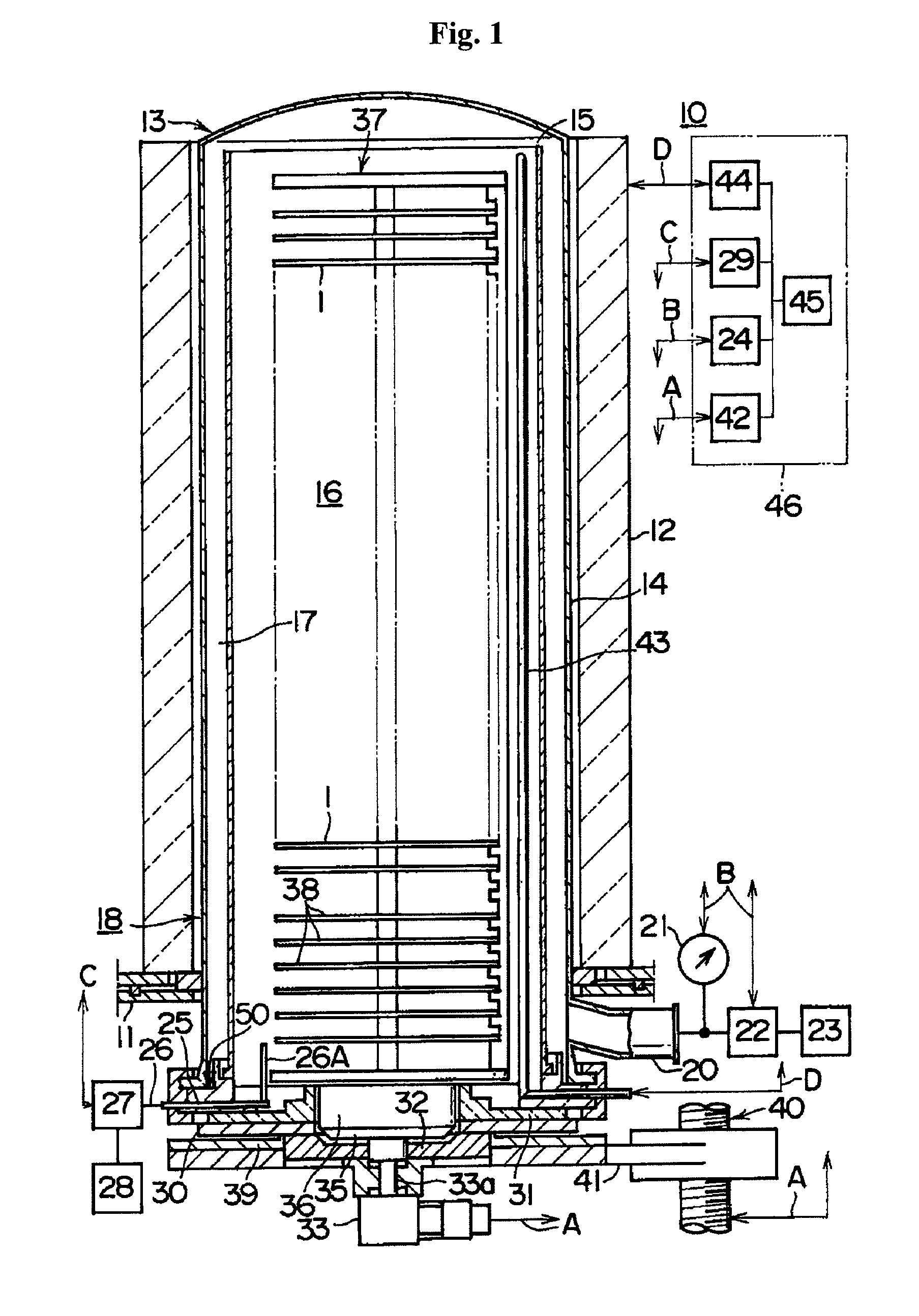
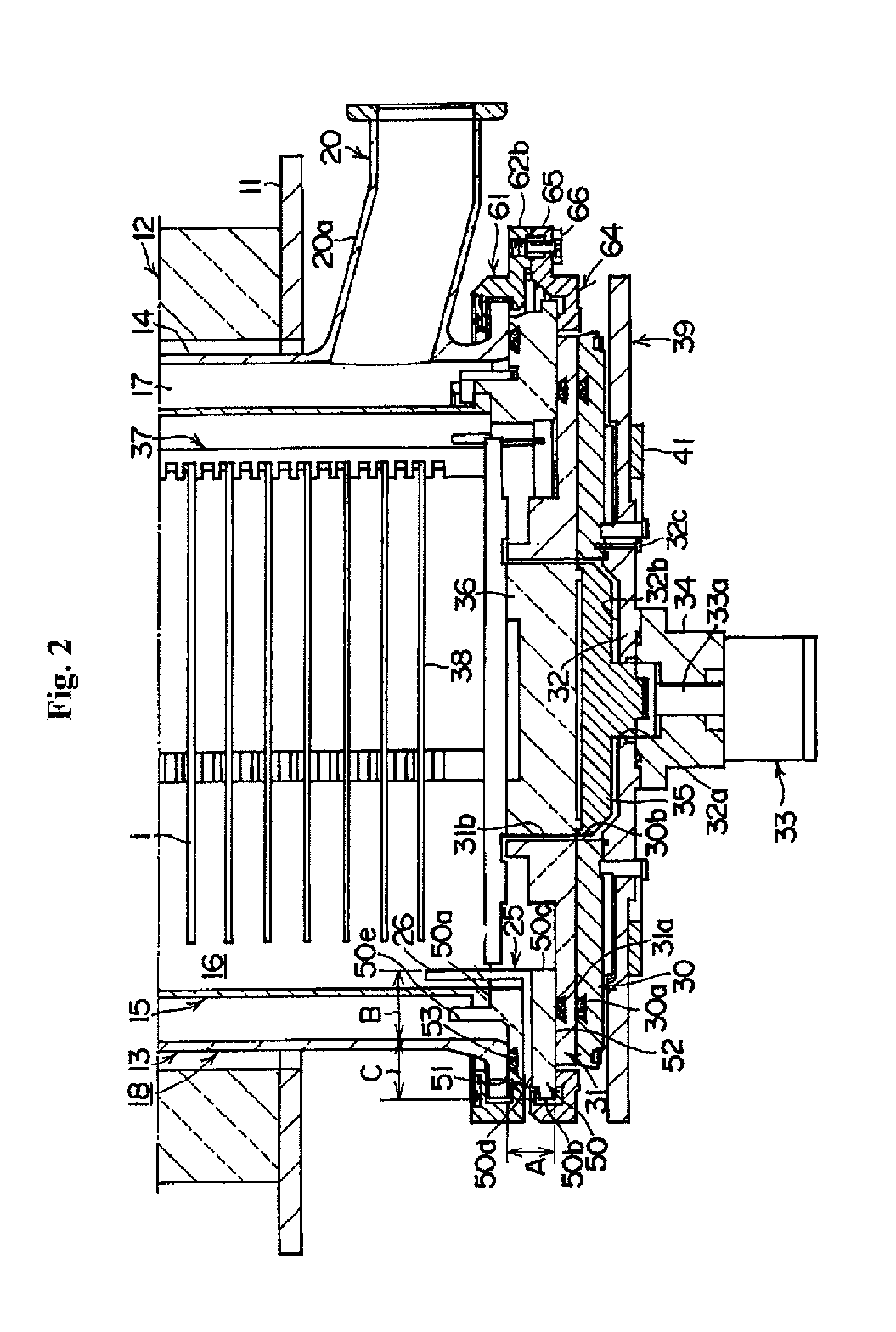
[0029]As shown in FIG. 1, a CVD apparatus 10 includes a heater 12 as a heating device.

[0030]The heater 12 has a cylindrical shape and is vertically installed in a manner such that the heater 12 is supported on a heater base 11 used as a holding plate.

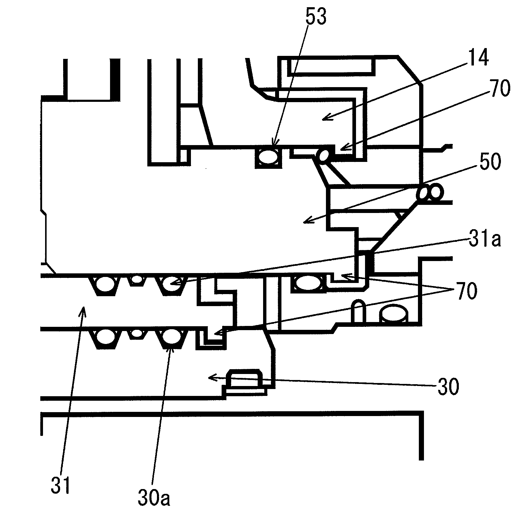
[0031]At the inside of the heater 12, a process tube 13 is installed coaxially with the heater 12 as a reaction tube. The process tube 13 includes an outer tube 14 used as an outer reaction tube and an inner tube 15 used as an inner reaction tube.

[0032]The outer tube 14 is made of quartz (SiO2) and has a cylindrical shape with an inner diameter greater than the outer diameter of the ...


PUM

PropertyMeasurementUnit
temperatureaaaaaaaaaa
shapeaaaaaaaaaa

Abstract

A substrate processing apparatus includes a reaction tube, the reaction tub including an inner tube made of quartz and an outer tube made of quartz; a manifold made of quartz disposed under the outer tube, a top surface of the manifold being in air-tight contact with a bottom surface of the outer tube via a sealing member; a seal cap cover made of quartz disposed under the manifold, a top surface of the seal cap cover being in air-tight contact with a bottom surface of the manifold via a sealing member; a seal cap covered by the seal cap cover, a top surface of the seal cap being in air-tight contact with a bottom surface of the seal cap cover via a sealing member; and at least one protrusion disposed at the bottom surface of one of the outer tube, the manifold, the seal cap cover, and combinations thereof.

Description

CROSS-REFERENCE TO RELATED PATENT APPLICATION[0001]This U.S. non-provisional patent application claims priority under 35 U.S.C. §119 of Japanese Patent Application No. 2008-219724, filed on Aug. 28, 2008, in the Japanese Patent Office, the entire contents of which are hereby incorporated by reference.BACKGROUND OF THE INVENTION[0002]1. Field of the Invention[0003]The present invention relates to a substrate processing apparatus.[0004]For example, the present invention may be effectively applied to a heat treatment apparatus (furnace) configured to perform a heat treatment process, such as film forming, annealing, oxidation, diffusion, and reflow treatment for carrier activation or planarization after ion implantation, so as to form an oxide film, a metal film, or a semiconductor film on a semiconductor wafer (hereinafter, referred to as a wafer) for forming a semiconductor integrated circuit device (hereinafter, referred to as an IC) on the wafer.[0005]2. Description of the Prior Ar...

Claims


Application Information

Patent Timeline
Patent Type & Authority Patents(United States)
IPC IPC(8): C23C16/455H01L21/306C23F1/00C23C16/06
CPCC23C16/4412
Inventor MORITA, SHINYANAKADA, TAKAYUKIMATSUDA, TOMOYUKISAKASHITA, KEISUKE
Owner KOKUSA ELECTRIC CO LTD
Why Eureka
Try Eureka