
Adaptive motion search range determining apparatus and method

a technology of search range and determining apparatus, which is applied in the field of adaptive motion search range determining apparatus and method, can solve the problems of increasing the complexity of an image encoder, increasing the computation quantity, and excessively large search range affecting the image encoder

Inactive Publication Date: 2013-09-10
ELECTRONICS & TELECOMM RES INST
View PDF7 Cites 1 Cited by
  • Summary
  • Abstract
  • Description
  • Claims
  • Application Information

AI Technical Summary

Benefits of technology

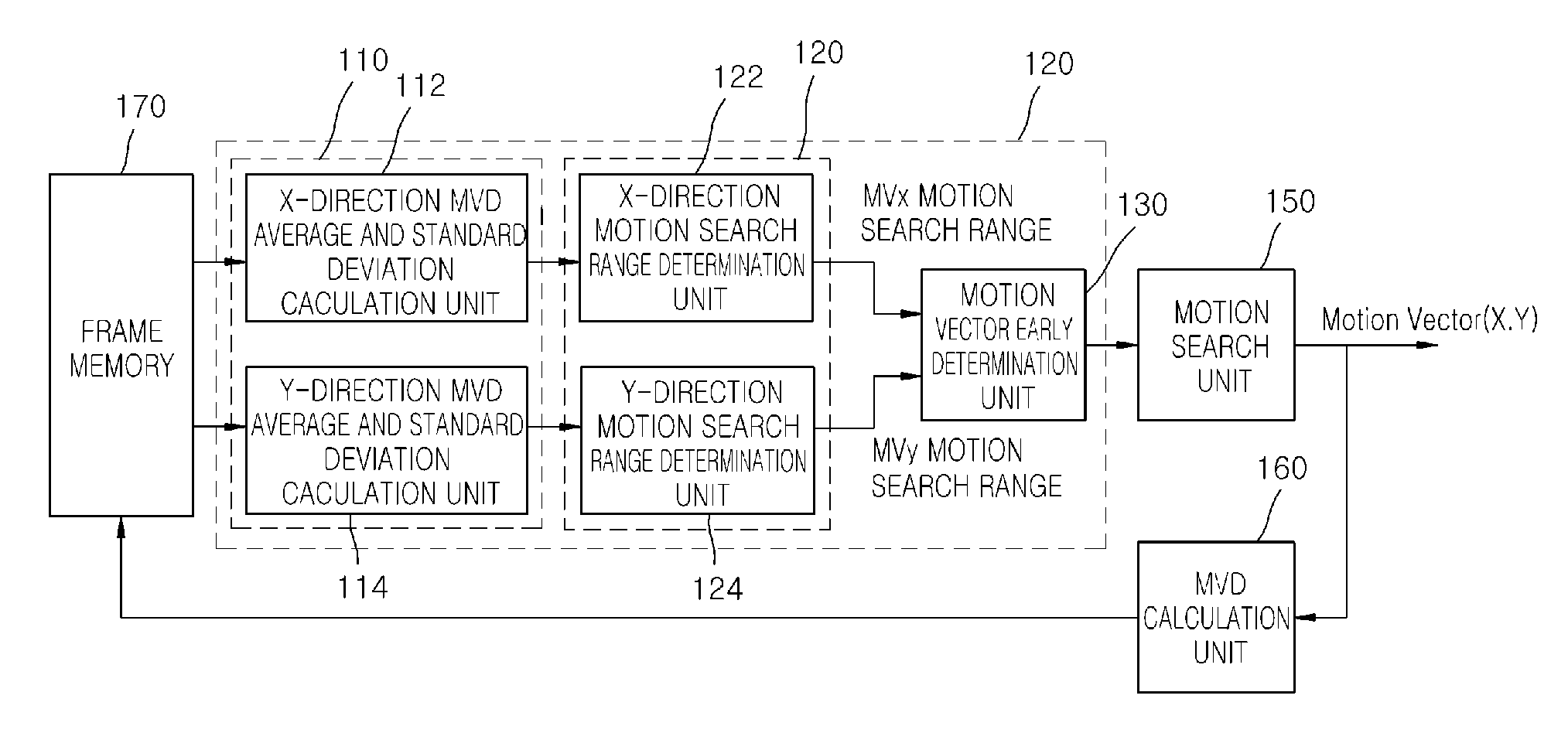
[0008]Embodiments of the present invention are directed to an adaptive motion search range determining apparatus and method, which enable each macroblock to have an adaptive search range by variably adjusting a search range of a motion vector with reference to neighboring motion vectors using the fact that a motion vector of a current macroblock is similar to motion vectors of neighboring macroblocks at the nearest positions.
[0009]Embodiments of the present invention are also directed to an adaptive motion search range determining apparatus and method, which are capable of minimizing image degradation during the motion searches of high-resolution images by variably adjusting search ranges for motion vectors, and are also capable of encoding high-resolution images such as UHD images by limiting motion searches in unnecessary areas and thus minimizing the computation quantities required for prediction of motion vectors.
[0012]In the present invention, the motion search range determination unit may update the motion search range of the current macroblock as the initially determined search range when the motion search range is greater or smaller than the initially determined search range.

Problems solved by technology

However, since the complexity of an image encoder also increases as the size of search range increases, an excessive large search range acts on the image encoder as a burden.
However, when images have not a lot of motions, there is a limitation in that the aforesaid method increases computation quantity because motion search is still performed in an unnecessary search range, thus making it difficult to realize real-time encoding.

Method used


Image

  • Adaptive motion search range determining apparatus and method
  • Adaptive motion search range determining apparatus and method
  • Adaptive motion search range determining apparatus and method

Examples


Embodiment Construction

[0026]Hereinafter, an adaptive motion search range determining apparatus and method in accordance with the present invention will be described in detail with reference to the accompanying drawings. Herein, the drawings may be exaggerated in thicknesses of lines or sizes of components for the sake of convenience and clarity in description. Furthermore, terms used herein are defined in consideration of functions in the present invention and may be varied according to the custom or intention of users or operators. Thus, definition of such terms should be determined according to overall disclosures set forth herein.

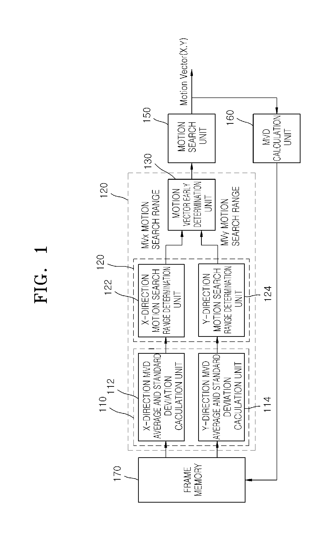
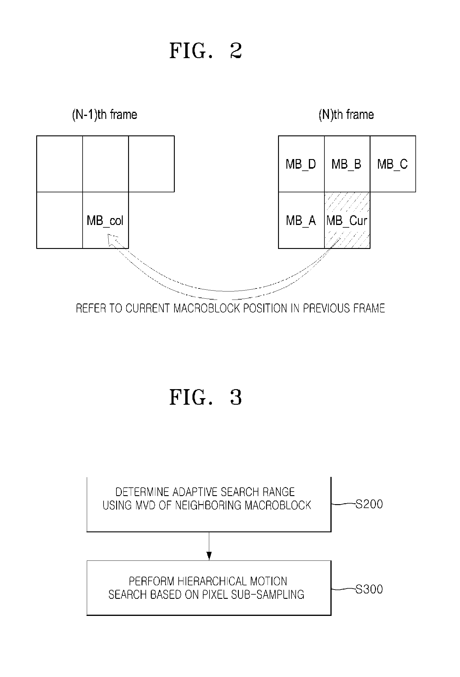
[0027]FIG. 1 illustrates a block diagram of a motion vector estimating apparatus according to an embodiment of the present invention, FIG. 2 illustrates neighboring macroblocks of a current macroblock according to an embodiment of the present invention, FIG. 3 illustrates a motion vector estimating method according to an embodiment of the present invention, and FIG. 4 illustr...


PUM


Abstract

Provided is an adaptive motion search range determining apparatus and method for encoding UHD-class high-resolution images. The adaptive motion search range determining apparatus includes an MVD average / standard deviation calculation unit calculating an value average and a standard deviation of MVDs of neighboring macroblocks of a current macroblock, and a motion search range determination unit determining a motion search range of the current macroblock using the value average and the standard deviation. According to the adaptive motion search range determining apparatus, it is possible to enable each macroblock to have an adaptive search range by variably adjusting a motion vector search range of a current macroblock with reference to motion vectors of neighboring macroblocks of the current macroblock.

Description

CROSS-REFERENCE TO RELATED APPLICATIONS[0001]The present application claims priority to Korean patent application number 10-2010-0116462, filed on Nov. 22, 2010, which is incorporated by reference in its entirety.BACKGROUND OF THE INVENTION[0002]The present invention relates to an adaptive motion search range determining apparatus and method, and more particularly, to an adaptive motion search range determining apparatus and method for encoding an image with high-resolution of Ultra High Definition (UHD) class, which enable each macroblock to have an adaptive search range by variably adjusting a motion vector search range of a current macroblock with reference to motion vectors of neighboring macroblocks of the current macroblock.[0003]High-speed of motion modules requiring a lot of computation quantities and hardware is especially essential to encode high-definition images in real-time. In the case of low-resolution images, enough efficiency could be obtained even though search ran...

Claims


Application Information

Patent Timeline
Patent Type & Authority Patents(United States)
IPC IPC(8): H04N7/50
CPCH04N19/57
Inventor LEE, SUK HOPARK, SEONG MOEUM, NAK WOONGJUNG, HEE-BUM
Owner ELECTRONICS & TELECOMM RES INST
Learn More