Image pickup apparatus capable of controlling exposure during motion with high shutter speed, including amplification of a signal obtained as a result of accumulating electric charge, control method therefor, and storage medium
a pickup apparatus and motion technology, applied in the field of image pickup apparatus, can solve problems such as noise in the image itself, and achieve the effects of reducing image degradation, reducing luminance changes, and high shutter speed
- Summary
- Abstract
- Description
- Claims
- Application Information
AI Technical Summary
Benefits of technology
Problems solved by technology
Method used
Image
Examples
first embodiment
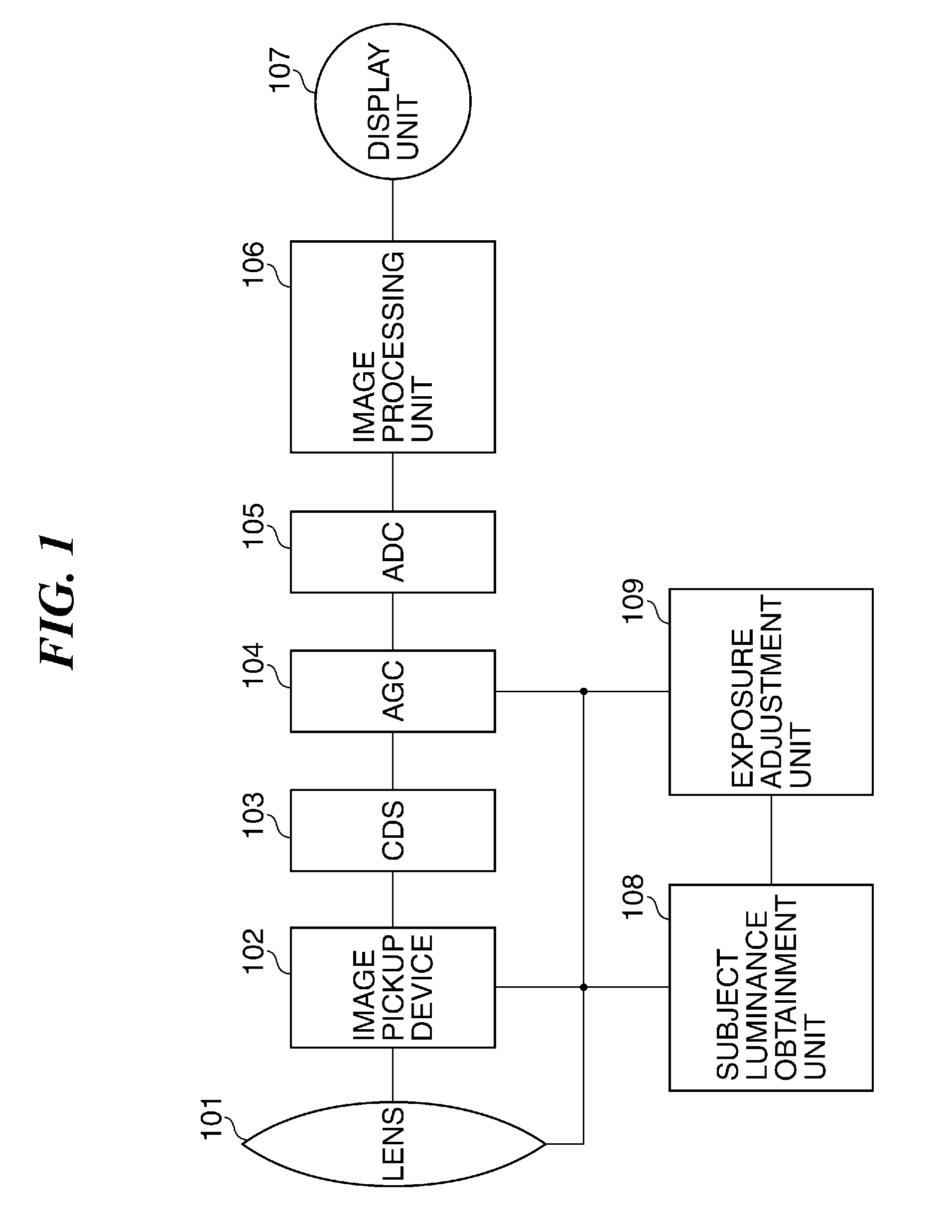
[0022]FIG. 1 is a block diagram schematically showing an arrangement of an exemplary image pickup apparatus according to a
[0023]Referring to FIG. 1, the image pickup apparatus has an image pickup device 102 such as a CCD or CMOS sensor. A subject image (optical image) is formed on the image pickup device 102 via a lens 101 comprised of several lenses. Then, the image pickup device 102 accumulates electric charges in accordance with an amount of light incident on the image pickup device 102 and outputs, as an output signal, an electric signal (analog signal) corresponding to the optical image. This electric signal (output signal) is subjected to processing by a correlated double sampling circuit (CDS) 103. It should be noted that although not shown in the figure, a diaphragm and a shutter are disposed at the lens 101 or between the lens 101 and the image pickup device 102.
[0024]An output from the CDS 103 (referred to as the CDS processed signal) is supplied to an automatic gain contr...
second embodiment
[0049]Next, a description will be given of an exemplary image pickup apparatus according to a
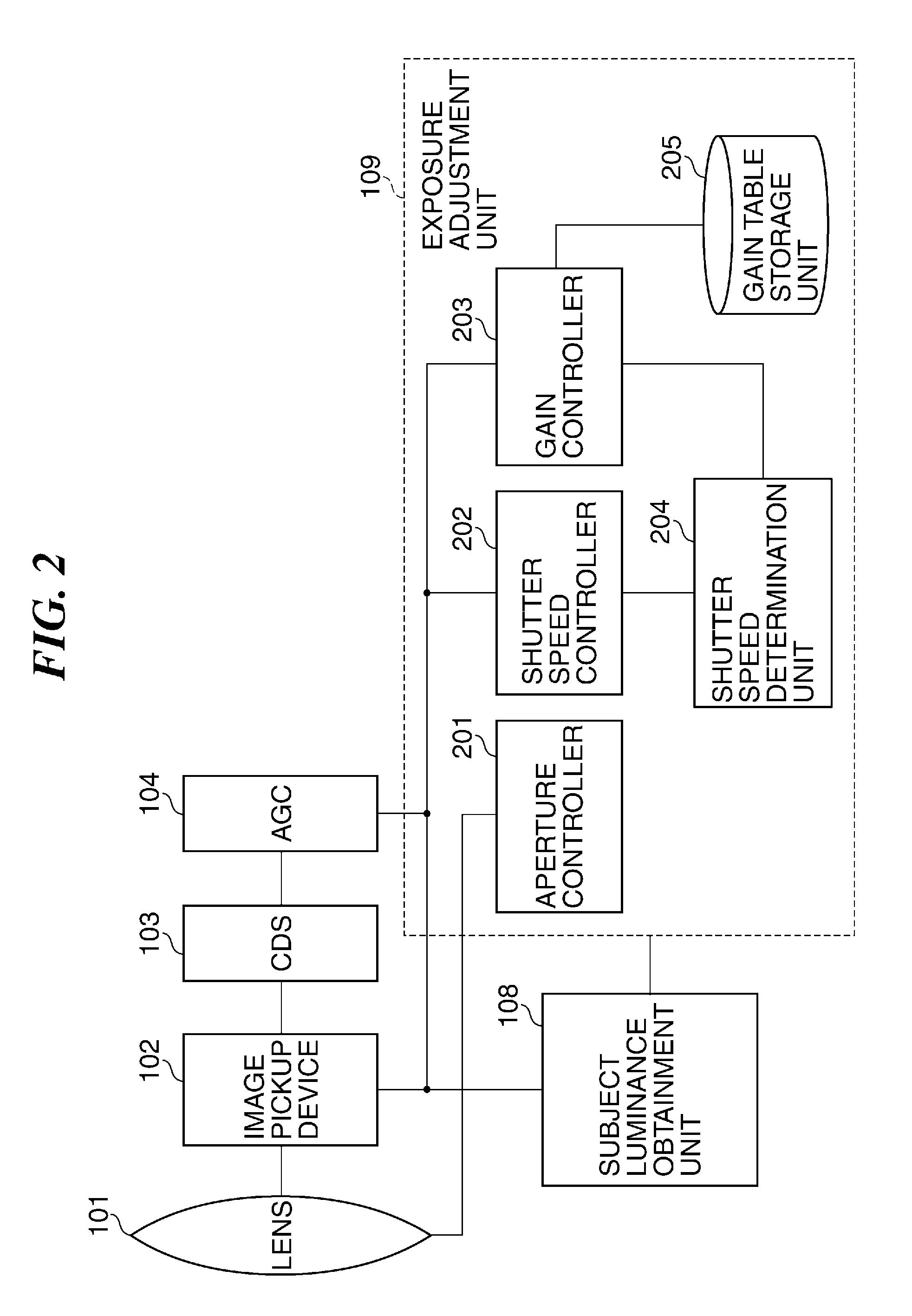
[0050]FIG. 5 is a block diagram schematically showing an arrangement of an exemplary image pickup apparatus according to the second embodiment. It should be noted that in FIG. 5, the same component elements as those shown in FIG. 2 are designated by the same reference numerals, and description thereof is omitted.
[0051]Referring to FIG. 5, the exposure adjustment unit 109 further has a shutter speed change detection unit 501. This shutter speed change detection unit 501 detects, as a shutter speed difference, a difference between a shutter speed one frame before and a present shutter speed. Then, the shutter speed determination unit 204 carries out a determination process, to be described later, according to the shutter speed difference.
[0052]FIG. 6 is a flowchart useful in explaining an exposure adjustment process carried out by the exposure adjustment unit 109 appearing in FIG. 5. It should...
PUM
 Abstract
Description
Claims
Application Information
 - R&D
- Intellectual Property
- Life Sciences
- Materials
- Tech Scout
- Unparalleled Data Quality
- Higher Quality Content
- 60% Fewer Hallucinations
Browse by: Latest US Patents, China's latest patents, Technical Efficacy Thesaurus, Application Domain, Technology Topic, Popular Technical Reports.
© 2025 PatSnap. All rights reserved.Legal|Privacy policy|Modern Slavery Act Transparency Statement|Sitemap|About US| Contact US: help@patsnap.com


