Image data generation method and device, and stencil printing apparatus, with density conversion based on pressing pressure based on recording medium width or thickness

a stencil printing and image data technology, applied in the field of image data generation, can solve the problems of image quality degradation, density stability impairment, and print contamination, and achieve the effect of avoiding blurring of fine or small characters or lines, and reducing image quality

Active Publication Date: 2013-09-17
RISO KAGAKU CORP
View PDF7 Cites 0 Cited by
  • Summary
  • Abstract
  • Description
  • Claims
  • Application Information

AI Technical Summary

Benefits of technology

[0013]In view of the above-described circumstances, the present invention is directed to providing a method and device for generating image data, as well as a stencil printing apparatus, with which an optimal amount of ink transfer onto a printing sheet is achieved regardless of the width and thickness of the printing sheet and local features of the original image, thereby minimizing such image degradation as insufficient density of prints due to insufficient printing pressure and contamination of prints due to strike-through, set-off or retransfer of ink.
[0020]Further, the image density conversion curve may provide a lower image density information value for a higher value of the information of image density in the reference area, and a ratio of decrease of a value of the converted image density information relative to increase of the value of the information of image density in the reference area may gradually increase along with increase of the value of the information of image density in the reference area, and then, the ratio of decrease may gradually decrease.
[0023]According to the method and device for generating image data as well as the stencil printing apparatus of the invention, a preset pressing pressure value, which is used when the image is recorded on the recording medium, is obtained based on the information of width and / or thickness of the recording medium, and information of image density in a reference area, which is apart of the image data, is obtained. Then, converted image density information is obtained by converting the information of image density in the reference area based on the pressing pressure value and the information of image density, and image data is generated according to the thus obtained converted image density information. Therefore, an optimal amount of ink transfer onto a printing sheet is achieved regardless of the width and thickness of the printing sheet and local features of the original image, thereby minimizing such image degradation as insufficient density of prints due to insufficient printing pressure and contamination of prints due to strike-through, set-off or retransfer of ink.
[0025]Further, in the case where determination is made as to whether or not image data in the reference area is image data representing a photographic picture and the method used to convert the information of image density is changed according to the result of the determination, the image density conversion processing is applied to the multivalued image data at an area where tone is important, and thus degradation of image quality due to interference between the pattern of the binary image and the pattern of the thinning-out, which is caused by applying the thinning-out processing to the binary image data, can be avoided. On the other hand, at an area where resolution is important, the thinning-out processing is applied to the binary image data, thereby avoiding blurring of fine or small character or line, which is the case when the image density conversion processing is applied to the multivalued image data.

Problems solved by technology

With the stencil printing apparatuses as described above, problem of contamination of prints may occur due to so-called “strike through”, “set-off”, retransfer of ink, etc., when the ink is excessively transferred onto the printing sheet, for example.
However, with the above-described method that involves reducing the pressing pressure, although the amount of ink transfer can be reduced, density stability is impaired and the image quality is degraded if the pressing pressure is excessively low.
Further, even when the amount of ink transfer is controlled in the manner as in the method disclosed in Patent Document 1, the printing pressure applied from the pressing roller to the printer drum varies when printing sheets having different thicknesses and widths are used, and thus an optimal amount of ink transfer may not necessarily be achieved.
Therefore, when conditions of the printing sheets vary, it is impossible to achieve an optimal amount of ink transfer, and this may result in prints with insufficient density or prints with contamination due to the ink retransfer.

Method used


Image

  • Image data generation method and device, and stencil printing apparatus, with density conversion based on pressing pressure based on recording medium width or thickness
  • Image data generation method and device, and stencil printing apparatus, with density conversion based on pressing pressure based on recording medium width or thickness
  • Image data generation method and device, and stencil printing apparatus, with density conversion based on pressing pressure based on recording medium width or thickness

Examples


first embodiment

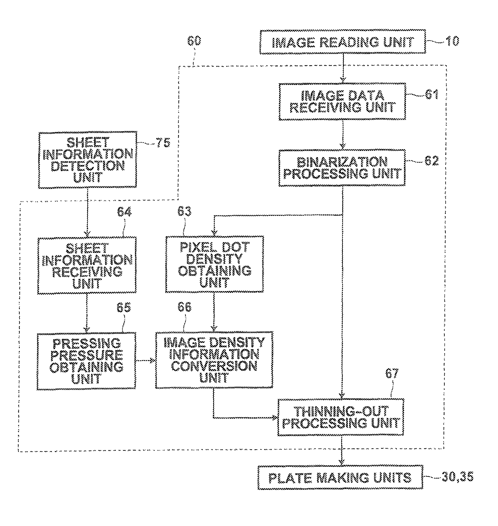
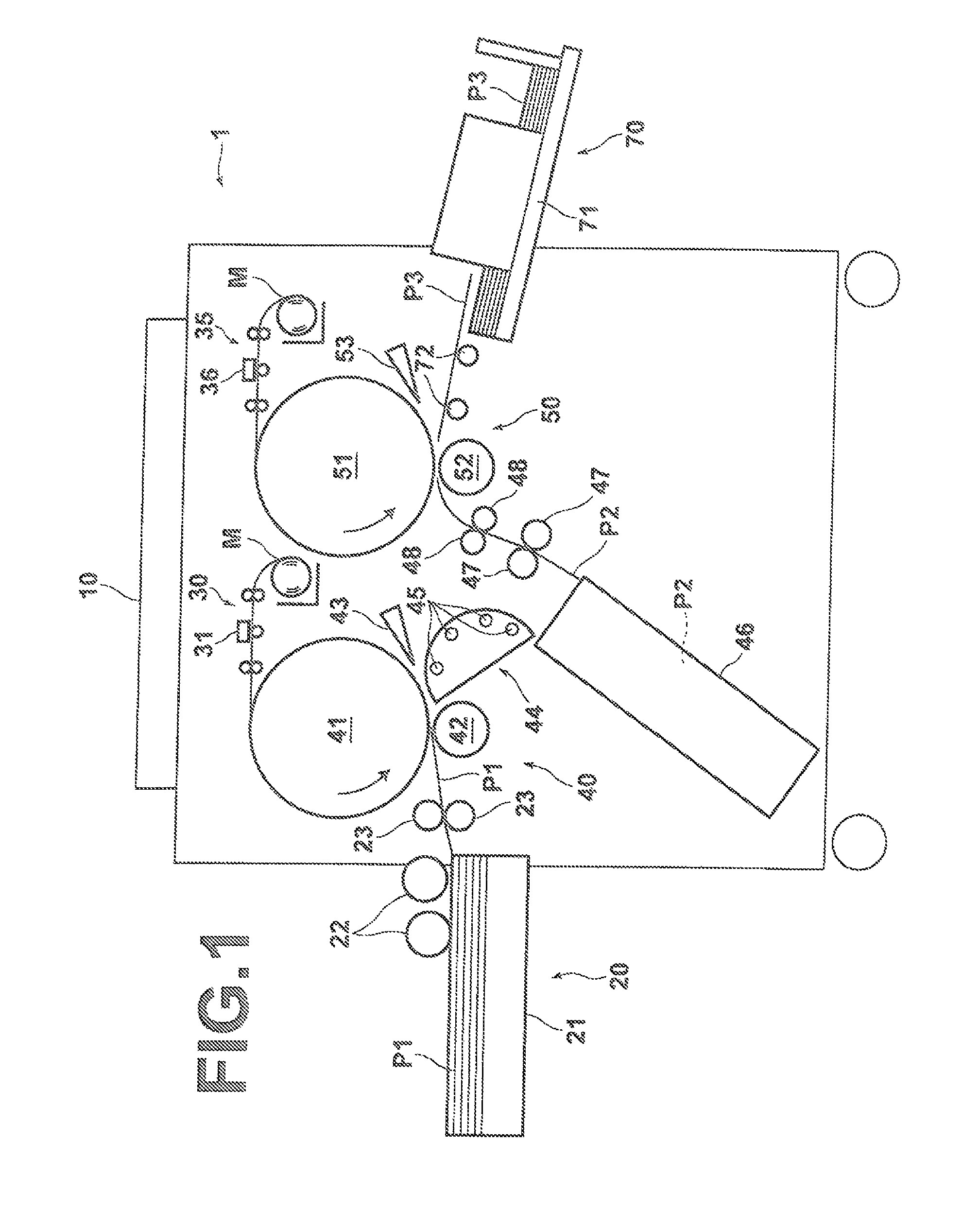
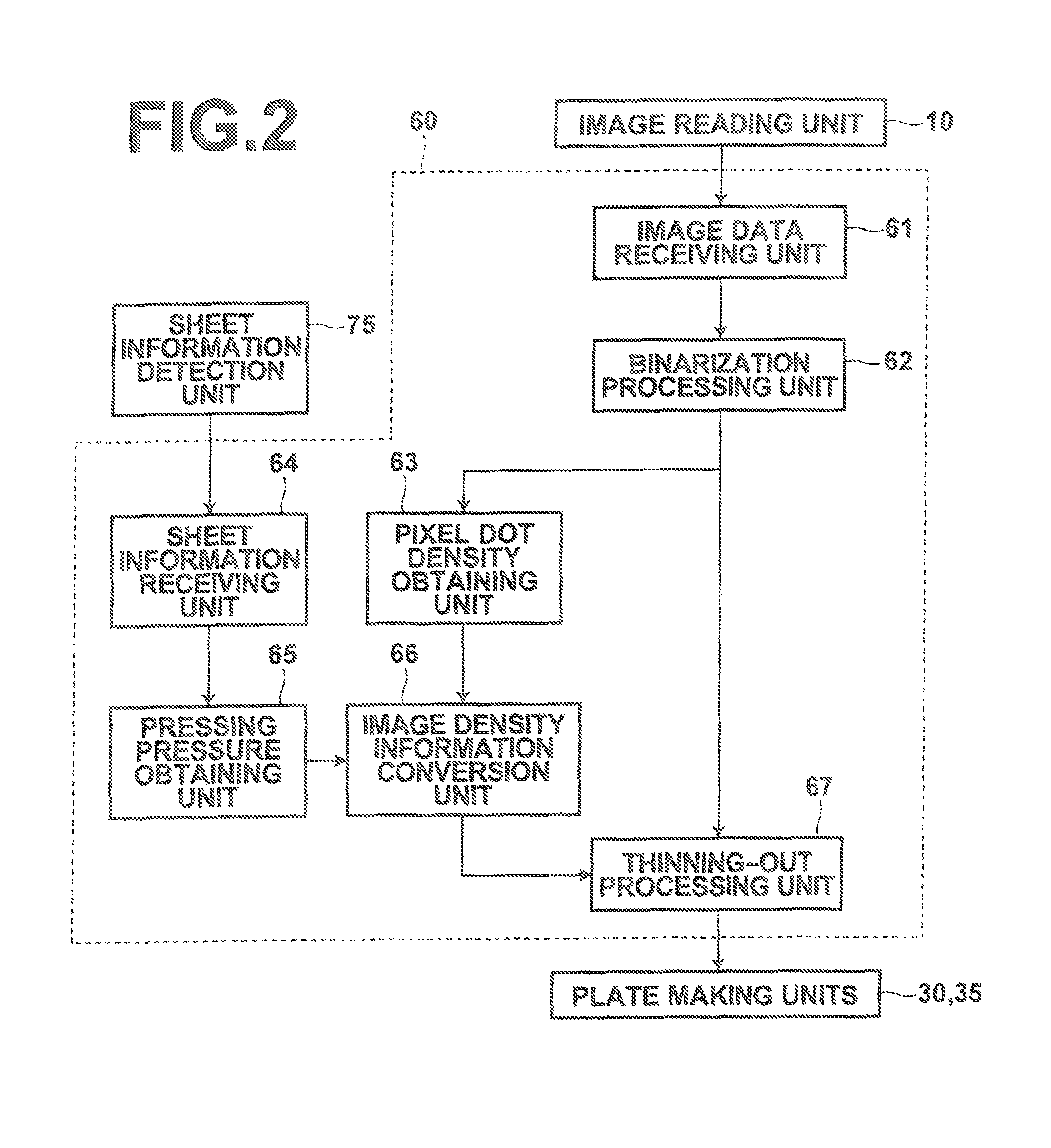
[0037]Hereinafter, a stencil printing apparatus employing an image data generation device of the present invention will be described in detail with reference to the drawings. The stencil printing apparatus of this embodiment is characterized by a method for generating image data. First, the schematic structure of the stencil printing apparatus is described. FIG. 1 is a diagram illustrating the schematic entire structure of the stencil printing apparatus of this embodiment.

[0038]As shown in FIG. 1, the stencil printing apparatus 1 of this embodiment includes: an image reading unit 10, which reads an image of an original document and outputs image data; first and second plate making units 30 and 35, which apply plate making processing to a stencil master sheet M based on the image data read by the image reading unit 10; first and second printing units 40 and 50, which carry out printing on a printing sheet P1 using the stencil master sheets M subjected to plate making at the first and...

second embodiment

[0091]Therefore, the image data generating unit of the stencil printing apparatus of the second embodiment carries out image density conversion processing at the photographic picture area, where tone is important, based on the multivalued image data.

[0092]Specifically, as shown in FIG. 9, the image data generating unit 80 of the stencil printing apparatus of the second embodiment includes: an image data receiving unit 81, which receives an input of the image data outputted from the image reading unit 10; an average image density obtaining unit 88, which obtains an average image density value in the reference area, which is a part of the image data received by the image data receiving unit 81; an image density conversion processing unit 89, which obtains output image density of the multivalued image data in the reference area based on the pressing pressure value obtained by a pressing pressure obtaining unit 85 and the average image density value obtained by the average image density...


PUM


Abstract

An input of image data is received, and information of width and / or thickness of a recording medium, which receives an image representing the image data to be recorded thereon, is received. Then, a preset pressing pressure value, which is used when the image is recorded on the recording medium, is obtained based on the information of width and / or thickness, and information of image density in the reference area, which is a part of the image data, is obtained. Then, converted image density information is obtained by converting the information of image density in the reference area based on the pressing pressure value and the information of image density, and image data is generated according to the thus obtained converted image density information.

Description

BACKGROUND OF THE INVENTION[0001]1. Field of the Invention[0002]The present invention relates to a method and device for generating image data, which involve receiving input of image data and applying image density conversion processing to the image data, as well as a stencil printing apparatus.[0003]2. Description of the Related Art[0004]Various stencil printing apparatuses have been proposed. In stencil printing, a master sheet is produced through plate making processing using a thermal head, or the like, which is driven to melt and perforate a stencil master sheet according to image data obtained by reading an original document with a scanner, or the like. Then, the thus produced master sheet is wrapped around a printer drum and an ink is fed from the interior of the printer drum. The ink is transferred onto a printing sheet using a roller, or the like, to achieve printing.[0005]Among the stencil printing apparatuses as described above, stencil printing apparatuses that perform d...

Claims


Application Information

Patent Timeline
Patent Type & Authority Patents(United States)
IPC IPC(8): H04N1/407B41M1/12
CPCB41L13/06
Inventor HAKAMADA, JUNICHIOKADA, YOSHIYUKIKAWASHIMA, MASAHIRO
Owner RISO KAGAKU CORP
Why Eureka
Try Eureka