
Eyepiece lens and imaging apparatus

a technology which is applied in the field of eyepiece lens and imaging apparatus, can solve the problems of significant image degradation, aspheric lens has a high tendency of surface shape manufacturing error, and eyepiece lens of patent document 3 has a problem of increasing the entire length, so as to achieve the effect of reducing the size of the imaging apparatus and high image quality

Active Publication Date: 2017-05-16
FUJIFILM CORP
View PDF16 Cites 0 Cited by
  • Summary
  • Abstract
  • Description
  • Claims
  • Application Information

AI Technical Summary

Benefits of technology

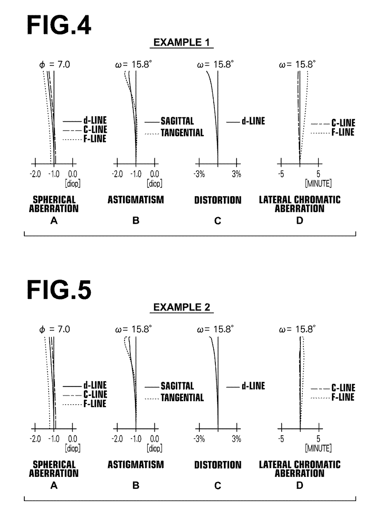
[0009]In view of the above-described circumstances, the present invention is directed to providing a compact eyepiece lens with minimized image degradation upon perpendicular shifting of the eye and minimized performance changes due to manufacturing errors of the surface shape while achieving successful correction of aberrations, as well as an imaging apparatus provided with the eyepiece lens.
[0024]The eyepiece lens of the invention consists of, in order from the observed object side: a first spherical lens having a positive refractive power; a second spherical lens having a negative refractive power; and a third lens having a positive refractive power with at least the observed object-side surface thereof having an aspheric shape, wherein the condition expression below is satisfied:0.0095<A3o / f3<0.0500  (1).This configuration allows providing a compact eyepiece lens with minimized image degradation upon perpendicular shifting of the eye and minimized performance changes due to manufacturing errors of the surface shape while achieving successful correction of aberrations.
[0025]The imaging apparatus of the invention is provided with the eyepiece lens of the invention. This allows providing a high image-quality view finder, and allows size reduction of the imaging apparatus.

Problems solved by technology

The eyepiece lenses proposed in Patent Documents 1 and 2, however, include two or more lenses having an aspheric surface and suffer significant image degradation when the eye is shifted in a direction perpendicular to the optical axis.
Further, aspheric lenses have a problem of high tendency of manufacturing errors of the surface shape.
However, the eyepiece lens of Patent Document 3 has a problem of increase of the entire length.

Method used


Image

  • Eyepiece lens and imaging apparatus
  • Eyepiece lens and imaging apparatus
  • Eyepiece lens and imaging apparatus

Examples


Embodiment Construction

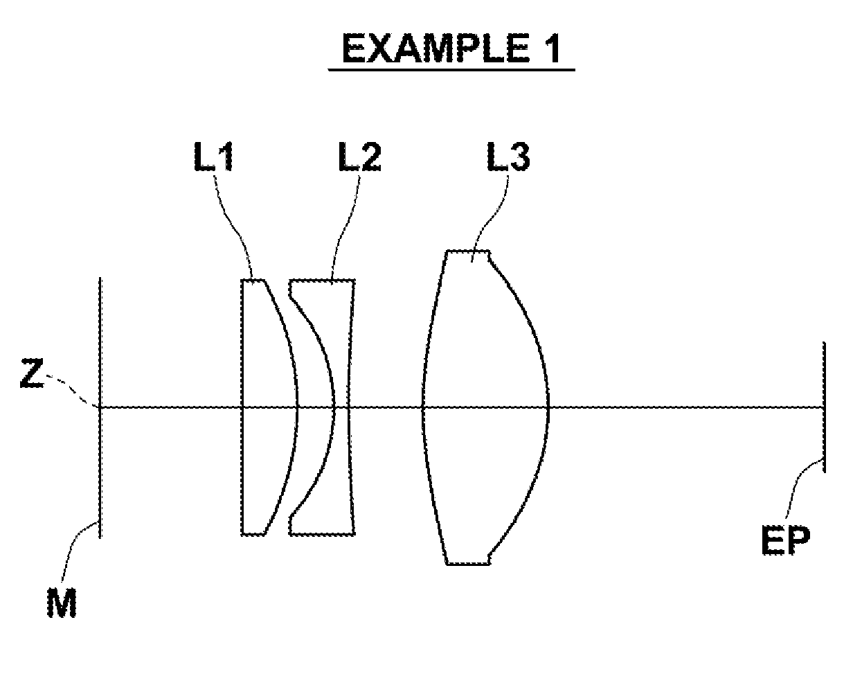
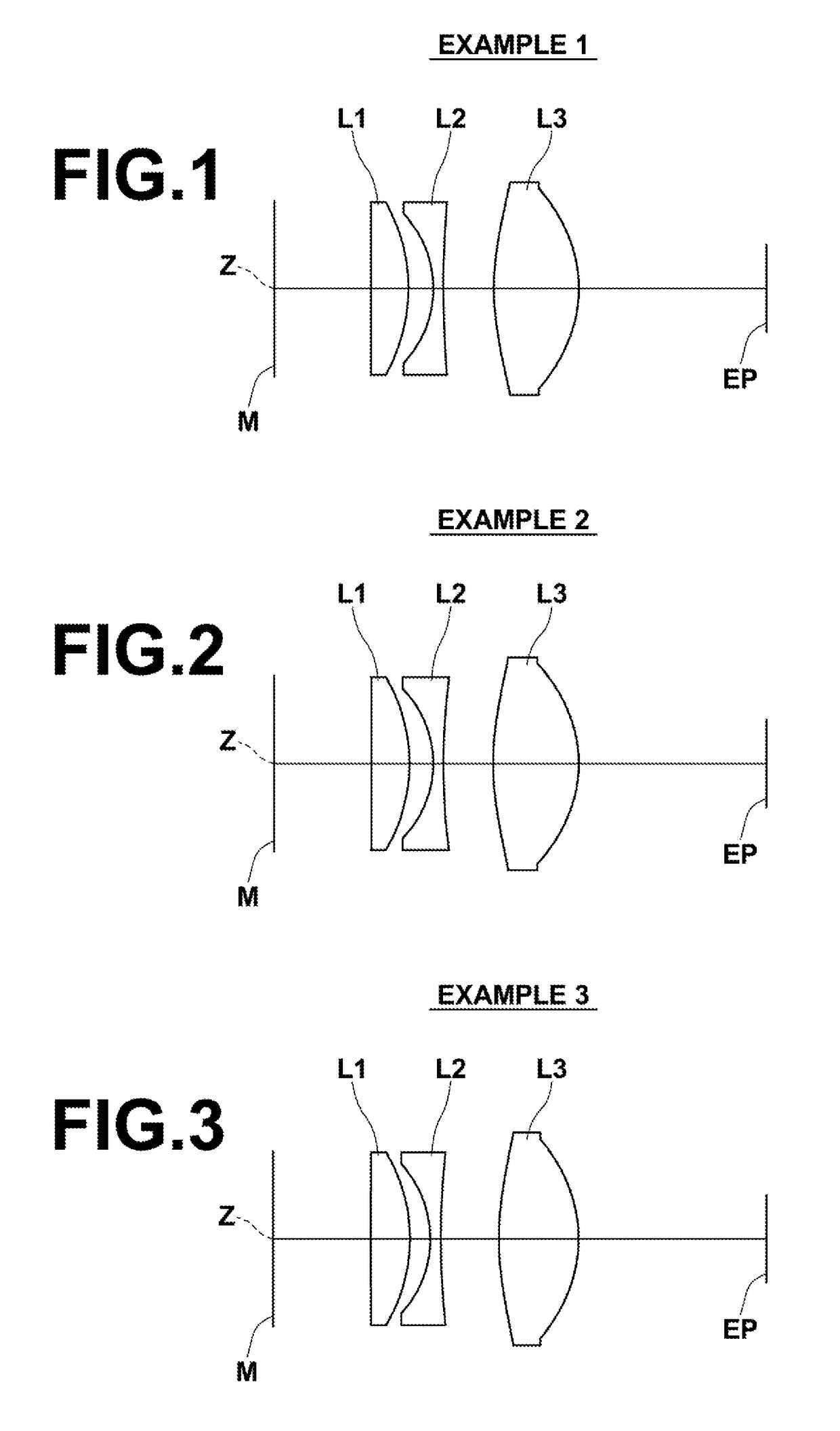
[0033]Hereinafter, embodiments of the present invention will be described in detail with reference to the drawings. FIG. 1 is a sectional view illustrating the lens configuration of an eyepiece lens according to one embodiment of the invention. The configuration example shown in FIG. 1 corresponds to an eyepiece lens of Example 1, which will be described later. In FIG. 1, the left side is the observed object side, and the right side is the eye point side.

[0034]This eyepiece lens consists of, in order from an observed object M side along the optical axis Z, a first spherical lens L1 having a positive refractive power, a second spherical lens L2 having a negative refractive power, and a third lens L3 having a positive refractive power with at least the observed object-side surface thereof having an aspheric shape.

[0035]Forming the first lens L1 and the second lens L2 by spherical lenses allows minimizing manufacturing errors of the lenses, and forming the third lens L3 by an aspheric ...


PUM


Abstract

An eyepiece lens consists of, in order from the observed object M side, a first spherical lens having a positive refractive power, a second spherical lens having a negative refractive power, and a third lens having a positive refractive power with at least the observed object-side surface thereof having an aspheric shape. The eyepiece lens satisfies the condition expression below:0.0095<A3o / f3<0.0500  (1).

Description

CROSS-REFERENCE TO RELATED APPLICATIONS[0001]This application is a Continuation of PCT International Application No. PCT / JP2013 / 005290 filed on Sep. 6, 2013, which claims priority under 35 U.S.C. §119(a) to Japanese Patent Application No. 2012-200136 filed on Sep. 12, 2012. Each of the above applications is hereby expressly incorporated by reference, in its entirety, into the present application.BACKGROUND OF THE INVENTION[0002]Technical Field[0003]The present invention relates to an eyepiece lens used to observe an image displayed on a display screen, and an imaging apparatus provided with the eyepiece lens.[0004]Background Art[0005]Electronic view finders (EVF) for use with cameras such as digital cameras or digital video cameras for observing an enlarged image of an image displayed on a liquid crystal display screen with a naked eye are conventionally proposed. Such an electronic view finder uses an eyepiece lens for observing an enlarged image of the liquid crystal display scree...

Claims


Application Information

Patent Timeline
Patent Type & Authority Patents(United States)
IPC IPC(8): G02B25/00G02B15/14G02B9/14G02B3/04
CPCG02B25/001G02B3/04
Inventor SAITO, HIROKI
Owner FUJIFILM CORP
Learn More