
Wiper blade

a technology of a wedge blade and a blade body, which is applied in the field of wedge blades, can solve the problems of large aerodynamic force, large aerodynamic force, and deterioration of the durability of the wedge blade, and achieve the effect of easy assembly

Inactive Publication Date: 2013-09-17
THE KOREA DEV BANK
View PDF21 Cites 3 Cited by
  • Summary
  • Abstract
  • Description
  • Claims
  • Application Information

AI Technical Summary

Benefits of technology

The present invention aims to improve the durability and performance of a wiper blade by reducing aerodynamic forces applied to it. It does this by designing a wiper blade with a spoiler that has a varying width in the longitudinal direction to allow air to flow smoothly by it. This reduces the bending and shape change of the spoiler, improving its overall performance and durability. Additionally, the reinforcing members embedded in the spoiler help maintain its shape and improve its attachment to the frame, ensuring better wipe performance. The locking groove in the either end of the spoiler makes it easy to assemble it onto the frame without using a separate fastening part.

Problems solved by technology

The large aerodynamic force is problematic since it causes a fatigue load and the deformation of the wiper blade while the vehicle is traveling and deteriorates the durability of the arm.
Further, the large aerodynamic force is also problematic since it can deform the spoiler of the wiper blade, which is composed of an elastic material and has an empty inside space, while the vehicle is traveling.
Furthermore, the large aerodynamic force during traveling of the vehicle may change the shape of the spoiler.
This may cause the wiper blade to conduct irregular wiping operations.

Method used


Image

  • Wiper blade
  • Wiper blade
  • Wiper blade

Examples


first embodiment

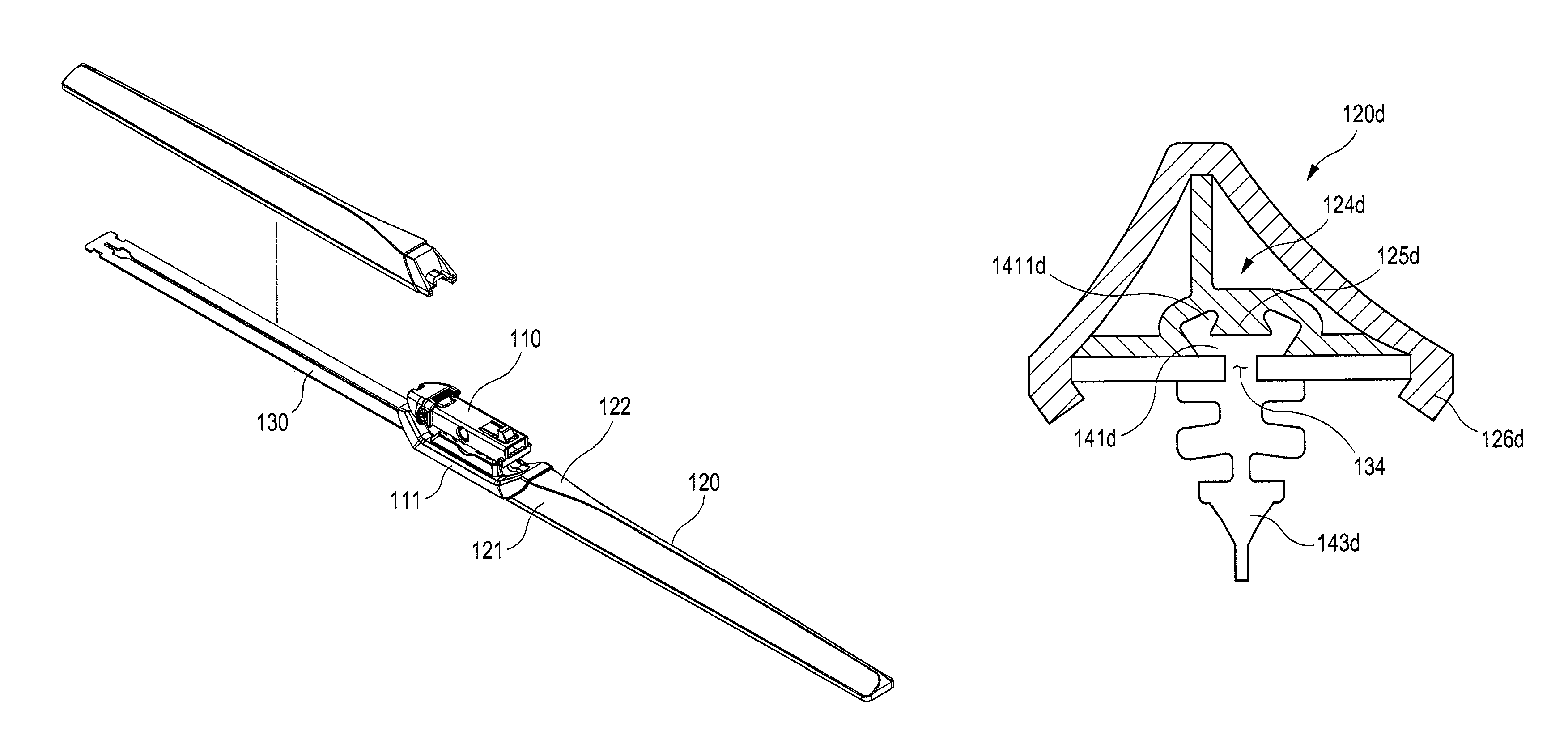
[0057]FIG. 10 is a cross-sectional view showing the reinforcing member provided in the spoiler. A reinforcing member 124a shown in FIG. 10 includes a flat plate formed inside a spoiler 120a.

[0058]Guide couplers 126a that extend inwardly from either a front lower end or a rear lower end of the spoiler 120 are formed in the spoiler to be coupled to the frame 130. When coupled, an upper surface of the frame 130 is placed in contact with a lower end of the reinforcing member 124a and lower front and rear ends of the frame 130 are coupled to the guide couplers 126a.

[0059]A head 141a of the wiper lip 140a has a convex cross section. The reinforcing member 124a includes a head seat 125a, which is concavely formed to correspond to the head 141a of the wiper lip 140a, at its lower midway end. The head 141a of the wiper lip 140a is fitted through a slit 134 of the frame 130 and is then firmly seated and fixed to the head seat 125a. This provides a fixed position of the wiper lip 140a and an...

second embodiment

[0060]FIG. 11 is a cross-sectional view showing the reinforcing member provided in the spoiler. A reinforcing member 124b shown in FIG. 11 includes a reinforcing frame that is formed inside a spoiler 120b. The reinforcing member 124b includes a vertical reinforcing frame 1241 extending downwardly from a top of the spoiler 120 and a horizontal reinforcing frame 1242 extending from front and rear ends of the spoiler 120b toward a center of the spoiler.

[0061]Coupling guides 126b that extend inwardly from either a front lower end or a rear lower end of the spoiler 120b are formed in the spoiler to be coupled to the frame 130. When coupled, the upper surface of the frame 130 is placed in contact with a lower end of the horizontal reinforcing frame 1242 and the lower front and rear ends of the frame 130 are placed in contact with lower surfaces of the guide couplers 126b.

[0062]A head 141b of the wiper lip 140b has a convex cross-section. The reinforcing member 124b includes a central rei...

third embodiment

[0063]FIG. 12 is a cross-sectional view showing the reinforcing member provided in the spoiler. The reinforcing member 124c shown in FIG. 12 is similar to the reinforcing member shown in FIG. 10. However, they are different in terms of the shapes of the following parts: guide couplers 126c for coupling to the frame 130; a head 141c of the wiper lip 140c; and a portion of the reinforcing member for seating the head thereto.

[0064]A U-shaped protrusion 1411c protrudes from the head 141c of the wiper lip 140c. The head seat 125c corresponding to the shapes of the protrusion 1411c and the head 141c is formed at a midway lower end of the reinforcing member 124c. The head 141c of the wiper lip 140c engages and is firmly fixed to the head seat 125c of the reinforcing member 124c. The protrusion 1411c of the head 141c is obliquely inclined with respect to the frame 130 such that the wiper lip 140c cannot fall out downwardly from the spoiler 120c.

[0065]The guide couplers 126c extend from bot...


PUM


Abstract

The present invention generally relates to a wiper blade for wiping a windshield, and more particularly to wiper blade including a spoiler that forms an air flow allowing the wiper blade to be in close contact with the windshield. The wiper blade according to the present invention has a frame, a spoiler receiving the frame therein and forming an upper surface of the wiper blade and a wiper lip extending downwardly from the frame to contact a windshield. The wiper blade includes the following: a frame including an adaptor coupler at a midway portion; a spoiler receiving the frame and provided next to either side of the adaptor coupler, the spoiler having a cross-section including leg sides of a front surface and a rear surface and a topside of a top surface; and an adaptor mounted to the adaptor coupler and connecting the frame to a wiper arm. A width of the top surface connecting the front surface and the rear surface of the spoiler is maximal near the adaptor coupler and becomes narrower toward a longitudinal end of the spoiler.

Description

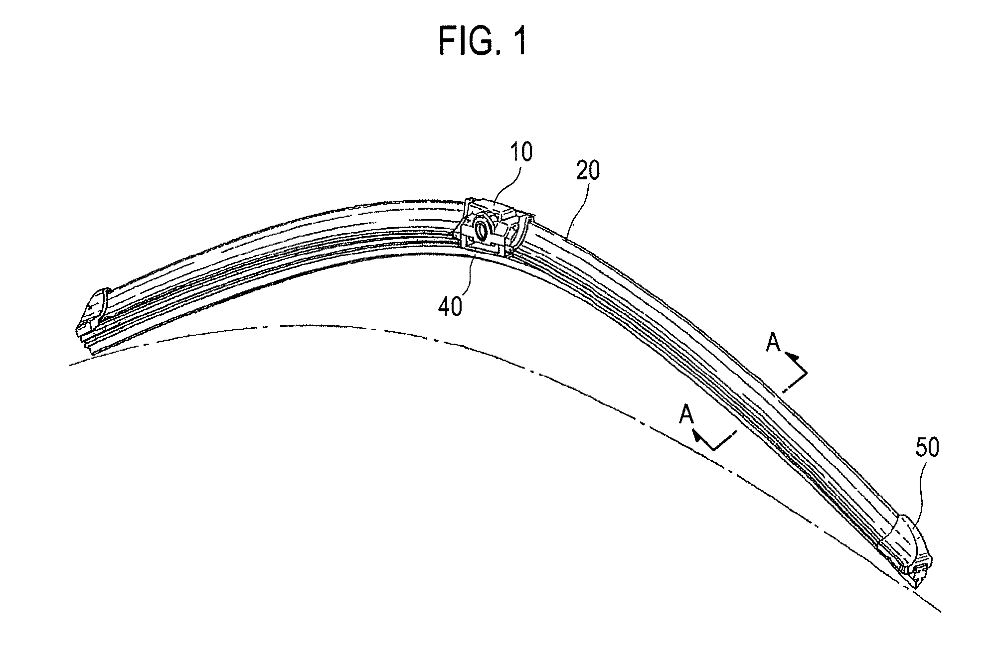
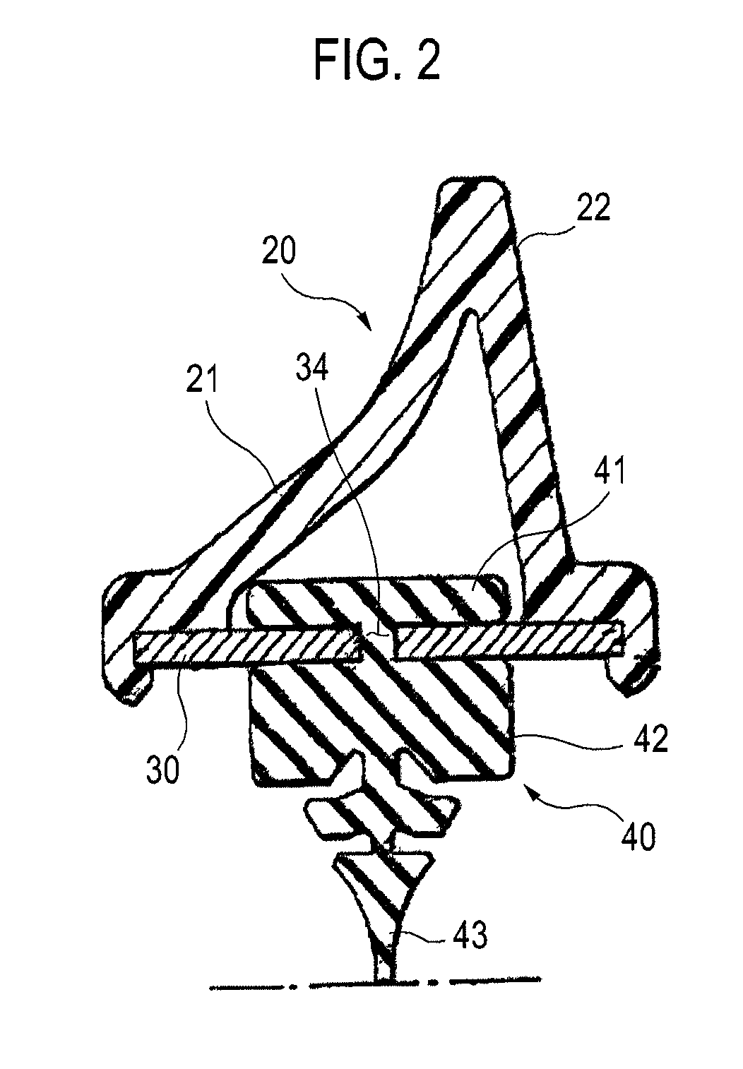
TECHNICAL FIELD[0001]The present invention generally relates to a wiper blade for wiping a windshield, and more particularly to a wiper blade having a spoiler that can minimize aerodynamic forces applied to the wiper blade while a vehicle is traveling.BACKGROUND OF THE INVENTION[0002]Generally, wiper blades are used to remove rainwater falling on a windshield of a car to ensure clear visibility. Further, wiper blades are also used to wipe off dirt stuck on the car windshield. Recently, there has been introduced in the art a wiper blade including a straight frame and a spoiler attached to the frame. The spoiler is designed to reduce resistance applied to the wiper blade while the car is traveling.[0003]Explanation will be made hereinafter as to one example of prior art wiper blades with reference to FIGS. 1 and 2.[0004]FIG. 1 is a perspective view showing a prior art wiper blade. FIG. 2 is a sectional view taken along the line A-A of the wiper blade shown in FIG. 1.[0005]As shown in ...

Claims


Application Information

Patent Timeline
Patent Type & Authority Patents(United States)
IPC IPC(8): B60S1/40
CPCB60S1/3879B60S1/381B60S2001/3836B60S1/38
Inventor KIM, IN-KYU
Owner THE KOREA DEV BANK
Learn More