Perforation strategy for heterogeneous proppant placement in hydraulic fracturing

a proppant placement and hydraulic fracturing technology, applied in the direction of fluid removal, earthwork drilling and mining, borehole/well accessories, etc., can solve the problems of large increase in the effective hydraulic conductivity of the overall fracture, formation cracks and fractures, and limited control of the location of the pillars, so as to minimize the resulting porosity

Active Publication Date: 2013-09-24
SCHLUMBERGER TECH CORP
View PDF38 Cites 13 Cited by
  • Summary
  • Abstract
  • Description
  • Claims
  • Application Information

AI Technical Summary

Benefits of technology

[0012]Yet another embodiment is a method for heterogeneous proppant placement in a fracture in a fracturing layer including a slugging step involving injecting alternating slugs of thickened proppant-free fluid and proppant-carrying thickened fluid into the fracturing layer above fracturing pressure through a number of clusters of perforations in a wellbore in the fracturing layer, and causing the sequences of slugs of thickened proppant-free fluid and proppant-carrying thickened fluid injected through at least one pair of clusters to be separated by a region of injected proppant-free fluid. Again, the slugs of proppant-carrying thickened fluid form pillars of proppant upon fracture closure.

Problems solved by technology

When the pressure exceeds a threshold value, the formation cracks and fractures.
This results in a significant increase of the effective hydraulic conductivity of the overall fracture.
However, in these methods of heterogeneous proppant placement there may be limited control over the location of the pillars.
In addition, there is a tendency for the pillars to be very long and to extend the entire height of the fracture (assuming a vertical fracture) and so the channels between the pillars do not lead to the wellbore, and so cannot provide superior pathways from the formation all the way to the wellbore.

Method used


Image

  • Perforation strategy for heterogeneous proppant placement in hydraulic fracturing
  • Perforation strategy for heterogeneous proppant placement in hydraulic fracturing
  • Perforation strategy for heterogeneous proppant placement in hydraulic fracturing

Examples


Embodiment Construction

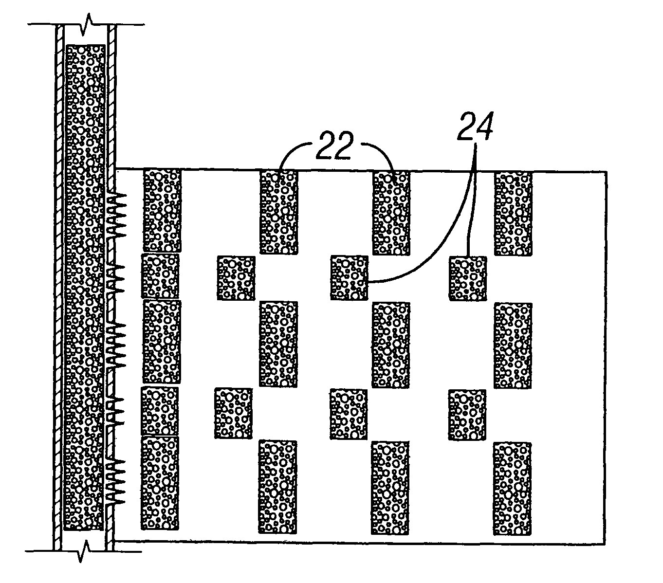
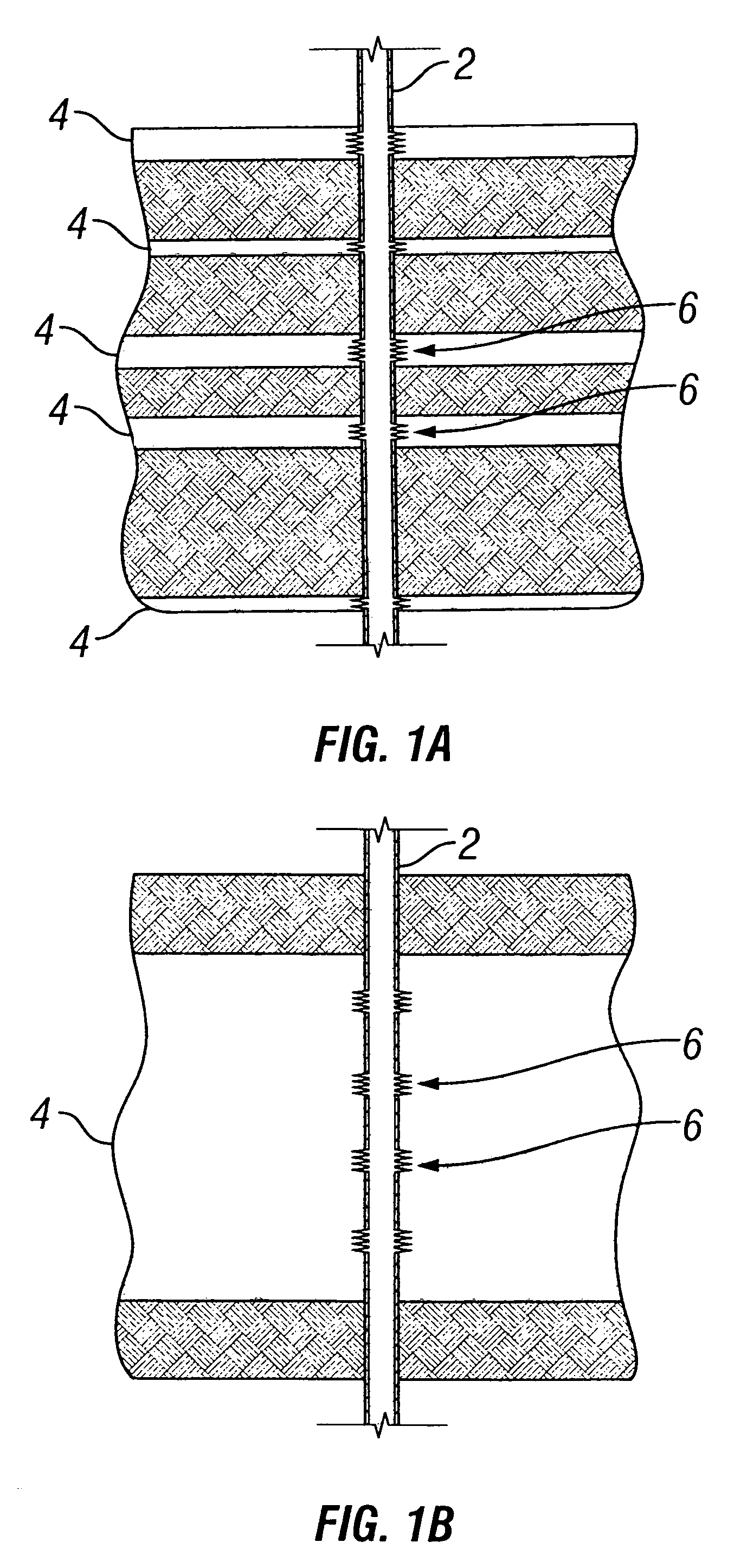
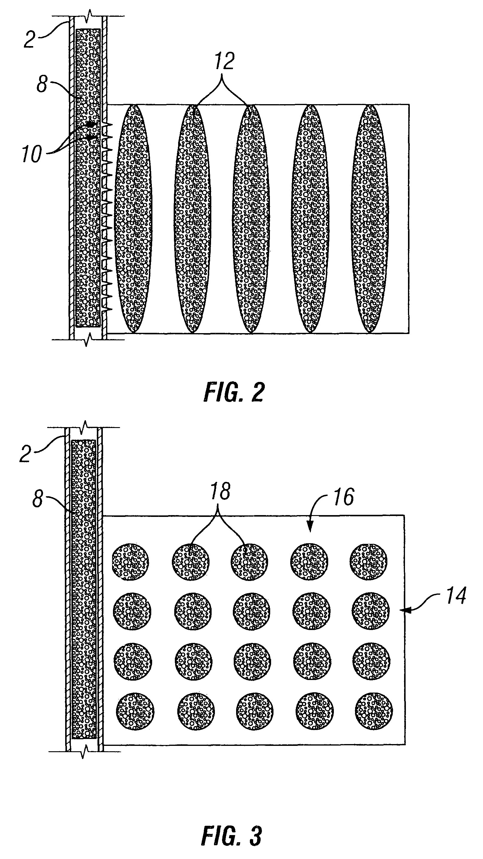
[0028]Some embodiments illustrating the invention will be described in terms of vertical fractures in vertical wells, but are equally applicable to fractures and wells of any orientation, as examples horizontal fractures in vertical or deviated wells, or vertical fractures in horizontal or deviated wells. The embodiments will be described for one fracture, but it is to be understood that more than one fracture may be formed at one time. Embodiments will be described for hydrocarbon production wells, but it is to be understood that the Invention may be used for wells for production of other fluids, such as water or carbon dioxide, or, for example, for injection or storage wells. The embodiments will be described for conventional hydraulic fracturing, but it is to be understood that embodiments of the invention also may include water fracturing and frac packing. It should also be understood that throughout this specification, when a concentration or amount range is described as being ...


PUM


Abstract

Hydraulic fracturing an individual reservoir fracturing layer of a subterranean formation to produce heterogeneous proppant placement is given in which pillars of proppant are placed such that the pillars do not extend the entire height of the fracture (for a vertical fracture) but are themselves interrupted by channels so that the channels between the pillars form pathways that lead to the wellbore. The method combines methods of introducing slugs of proppant-carrying and proppant-free fluids through multiple clusters of perforations within a single fracturing layer of rock, with methods of ensuring that the slugs exiting the individual clusters do not merge.

Description

CROSS-REFERENCE TO RELATED APPLICATIONS[0001]This application claims the benefit of PCT / RU2007 / 000357, filed on Jul. 3, 2007, which is incorporated herein by reference in its entirety.BACKGROUND[0002]The statements in this section merely provide background information related to the present disclosure and may not constitute prior art.[0003]The invention relates to production of fluids from subterranean formations. More particularly, it relates to stimulation of flow through formations by hydraulic fracturing. Most particularly, it relates to methods of optimizing fracture conductivity by propping fractures in a formation stratum so that the proppant is distributed heterogeneously in the fracture, and in some embodiments, the fracture containing substantial voids with little or no proppant.[0004]Hydraulic fracturing is a primary tool for improving well productivity by placing or extending highly conductive fractures from the wellbore into the reservoir. Conventional hydraulic fractur...

Claims


Application Information

Patent Timeline
Patent Type & Authority Patents(United States)
IPC IPC(8): E21B43/267
CPCE21B43/267E21B43/11
Inventor KOSAREV, IVAN VITALIEVICHMEDVEDEV, OLEG OLEGOVICHMEDVEDEV, ANATOLY VLADIMIROVICHWALTON, IAN
Owner SCHLUMBERGER TECH CORP
Why Eureka
Try Eureka