

Compositions, methods, apparatus, and systems for incorporating bio-derived materials in drilling and hydraulic fracturing
a technology of bio-derived materials and hydraulic fracturing, which is applied in the direction of fluid removal, chemistry apparatus and processes, and borehole/well accessories, etc., can solve the problems of reducing the amount of water used in the process, hydrofracturing, and oil-based fluids are subject to environmental scrutiny and are costly, so as to improve the environmental outlook of drilling and hydraulic fracturing, improve the effect of properties and improving the environmental outlook
- Summary
- Abstract
- Description
- Claims
- Application Information
AI Technical Summary
Benefits of technology
Problems solved by technology
Method used
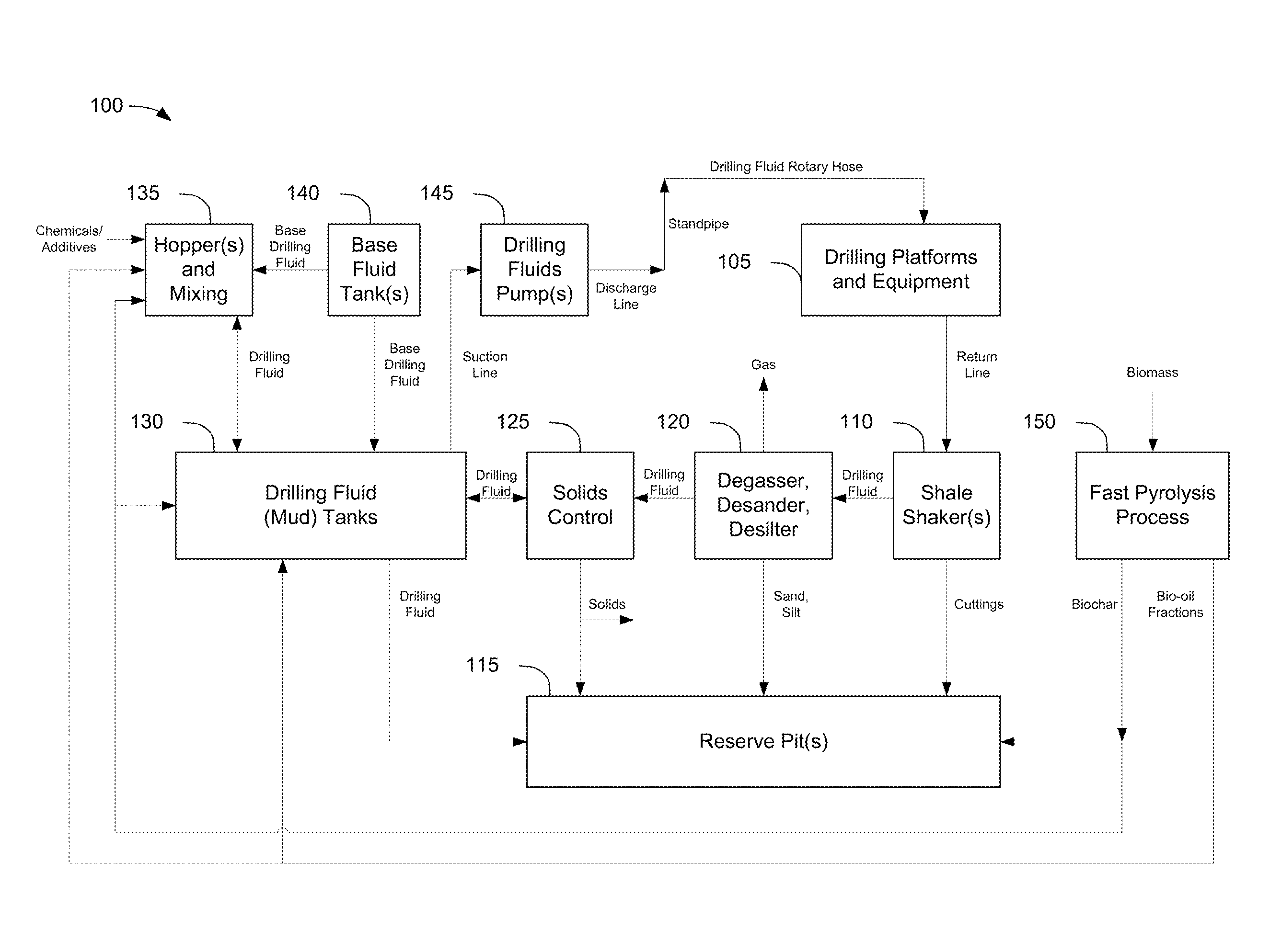
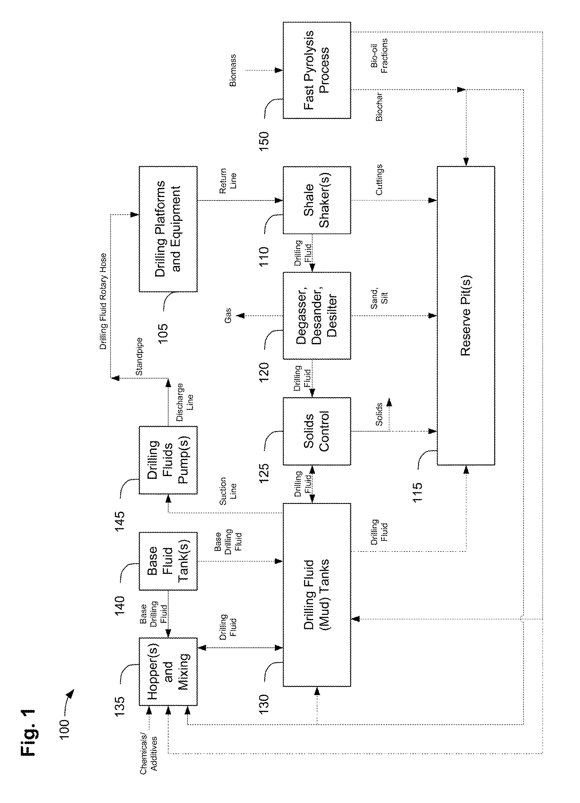
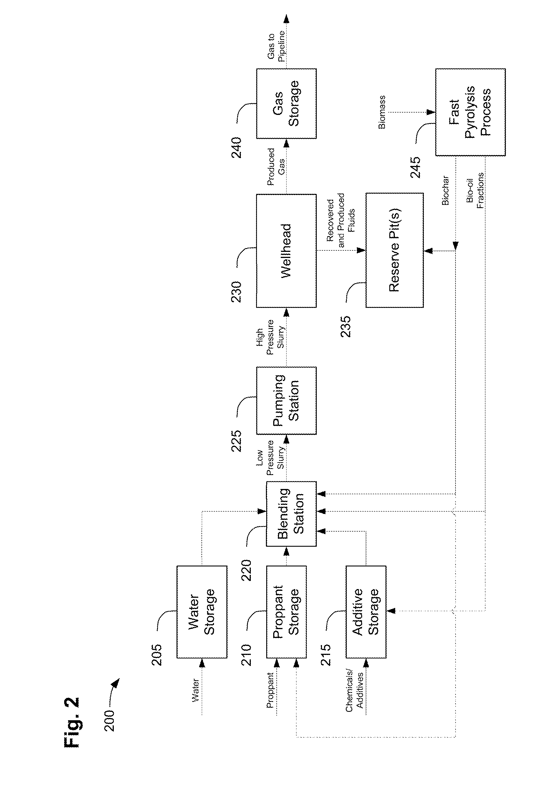
Image

Examples
example 1
Aqueous Phase of Bio-Oil Tested as a Breaker at 90° C.
[0150]Fracturing fluid samples treated with an aqueous phase pyrolysis liquid (water-rich fraction) breaker were prepared in a blender and analyzed to determine break time. A gelling agent containing a solution of 54 wt % guar gum powder and 46 wt % vegetable oil was hydrated in 0.5 liters of de-ionized water for 2 minutes. Each sample was treated with a quantity of aqueous phase pyrolysis liquid breaker diluted with de-ionized water (100:1) and 14 wt % sodium tetraborate / methanol solution to crosslink the gel. The aqueous phase pyrolysis liquid was produced from oak biomass using a pilot scale fast pyrolysis system described in U.S. Pat. No. 8,100,990. Sand, sieved between 20 and 30 mesh, was added to each sample after crosslinking to visually determine the time required to break the gel. A Brookfield DV-E rotational viscometer was used to confirm a visually broken gel by ensuring a viscosity below 50 cP at 90° C.
[0151]The aqueo...
example 2
Aqueous Phase of Bio-Oil Tested as a Breaker at 80° C.
[0153]Fracturing fluid samples treated with an aqueous phase pyrolysis liquid (water-rich fraction) breaker were prepared in a blender and analyzed to determine break time. A gelling agent containing a solution of 53 wt % guar gum powder and 47 wt % vegetable oil was hydrated in 0.5 liters of de-ionized water for 2 minutes. Each sample was treated with a quantity of aqueous phase pyrolysis liquid breaker diluted with de-ionized water (100:1) and 13 wt % sodium tetraborate / methanol solution to crosslink the gel. The aqueous phase pyrolysis liquid was produced from oak biomass using a pilot scale fast pyrolysis system described in U.S. Pat. No. 8,100,990. Sand, sieved between 20 and 30 mesh, was added to each sample after crosslinking to visually determine the time required to break the gel. A Brookfield DV-E rotational viscometer was used to confirm a visually broken gel by ensuring a viscosity below 50 cP at 80° C.
[0154]The aqueo...
example 3
Model Compounds Tested as a Breaker at 80° C.
[0156]Fracturing fluid samples treated with model compounds found in aqueous phase pyrolysis liquid were prepared in a blender and analyzed to determine break time. Acetic acid and methanol were found in a particular aqueous phase pyrolysis liquid at about 12 wt % and 1.6 wt %, respectively. Therefore, acetic acid and methanol were tested as model compound breakers once diluted with de-ionized water to concentrations similar to that found in diluted aqueous phase pyrolysis liquid. A gelling agent containing a solution of 53 wt % guar gum powder and 47 wt % vegetable oil was hydrated in 0.5 liters of de-ionized water for 2 minutes. Each was treated with a quantity and compound type analogous to diluted pyrolysis liquid, as shown in Table 4 and 13 wt % sodium tetraborate / methanol solution to cross link the gel. Sand, sieved between 20 and 30 mesh, was added to each sample after crosslinking to visually determine the time required to break t...
PUM
| Property | Measurement | Unit |
|---|---|---|
| viscosity | aaaaa | aaaaa |
| temperatures | aaaaa | aaaaa |
| wt % | aaaaa | aaaaa |
Abstract
Description
Claims
Application Information