Optimization method for efficiently laying propping agents in hydraulic fracturing operation

A technology for hydraulic fracturing and optimization methods, applied in design optimization/simulation, volume measurement instruments/methods, measurement devices, etc., can solve problems such as poor effect, low efficiency, and non-standard methods, and achieve comprehensive optimization results. Effects of interference, optimization results

Active Publication Date: 2021-05-07
SOUTHWEST PETROLEUM UNIV
View PDF10 Cites 2 Cited by
  • Summary
  • Abstract
  • Description
  • Claims
  • Application Information

AI Technical Summary

Problems solved by technology

But so far, the numerical simulation and optimal design of proppant particle placement mainly rely on empirical case reference and manual parameter adjustment. The method is not standardized, and its efficiency is low and the effect is not good.

Method used


Image

  • Optimization method for efficiently laying propping agents in hydraulic fracturing operation
  • Optimization method for efficiently laying propping agents in hydraulic fracturing operation
  • Optimization method for efficiently laying propping agents in hydraulic fracturing operation

Examples


Embodiment 1

[0097] Taking the 4th section of TL in Sichuan tight gas well as an example, the method of the present invention is further described.

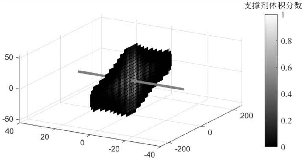
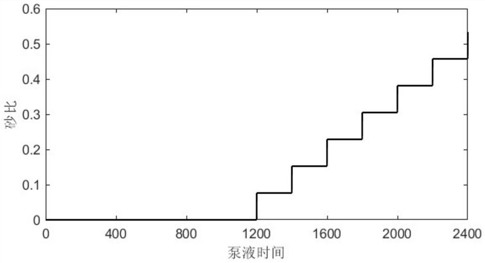
[0098] According to the mathematical model constructed in the above steps 1 and 2, calculate and predict the hydraulic fracture geometry and proppant volume concentration distribution after hydraulic fracturing. On the basis of the above model, characterize the pumped volume fraction of proppant according to the formula in step 2

[0099] The geological and engineering condition parameters of the fourth section of gas well TL are collected and sorted out, as shown in Table 3.

[0100] Table 3. Geological and engineering parameters of the fourth section of TL in an example tight gas well

[0101]

[0102] Based on L 16 The start time t of the 16 groups of pumping proppant listed in Orthogonal Table 1 c , the number n of proppant step slugs pumped and the average particle size of proppant particles a, the fracture geometry and proppant ...

Embodiment 2

[0113] Taking the fourth section of tight oil well X2 as an example, the method of the present invention is further described.

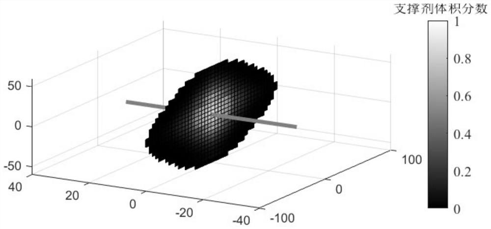
[0114] According to the mathematical model constructed in the above steps 1 and 2, calculate and predict the hydraulic fracture geometry and proppant volume concentration distribution after hydraulic fracturing. On the basis of the above model, characterize the pumped volume fraction of proppant according to the formula in step 2

[0115] The geological and engineering condition parameters of the first section of oil well X2 were collected and sorted out, as shown in Table 5.

[0116] Table 5. Geological and engineering parameters of the first section of tight oil well in Example 2

[0117]

[0118] The fracturing section is planned to pump 8m 3 Quartz sand proppant, based on L 16 The start time t of the 16 groups of pumping proppant listed in Orthogonal Table 1 c , the number n of proppant step slugs pumped and the average particle size of ...


PUM


Abstract

The invention discloses an optimization method for efficiently laying propping agents in hydraulic fracturing operation. The optimization method comprises the following steps that 1, a rock deformation control equation and a fracturing fluid flowing and propping agent migration material balance equation in the fracturing process are constructed; 2, a model used for representing the pumping volume fraction of the propping agents is constructed; 3, parameters are given, and the corresponding fracture geometric dimension and propping agent volume concentration distribution are obtained through calculation; 4, the laying efficiency of each group of propping agents is calculated; 5, the average propping agent laying efficiency of each group is calculated; 6, optimization parameters are selected; and 7, the propping agent pumping volume fraction changing along with time is calculated; and the result is substituted into the model in the step 1 for calculation, the calculated propping agent laying efficiency after fracturing is obtained, and whether the optimization parameters are optimal or not is verified. The optimization method has the advantages that the hydraulic fracturing propping agent laying effect can be improved, and the oil and gas productivity can be improved.

Description

technical field [0001] The invention relates to the technical field of oil and gas field development, in particular to an optimization method for efficiently laying proppants in hydraulic fracturing operations. Background technique [0002] For low-permeability oil and gas reservoirs, hydraulic fracturing is one of the most effective stimulation techniques. By pumping high-pressure fluid carrying proppant particles into the oil and gas well, the hydraulic fracturing process aims to induce the formation of hydraulic fractures with a certain width in the reservoir rock, build a high-speed channel for oil and gas flow, and increase the production of low-permeability oil and gas reservoirs. When the hydraulic fracturing operation is completed, the hydraulic fractures formed in the ground will quickly close under the high formation pressure. At this time, the permeability of the fracture area not effectively covered by proppant particles will be greatly reduced, making it diffic...

Claims


Application Information

Patent Timeline
Patent Type & Authority Applications(China)
IPC IPC(8): E21B43/26E21B43/267E21B47/00G06F30/20G06Q50/02
CPCE21B43/26E21B43/267E21B47/00G06Q50/02G06F30/20E21B2200/20G01F22/00
Inventor 陈曦宇李勇明赵金洲文汇博付斌于智博
Owner SOUTHWEST PETROLEUM UNIV
Why Eureka
Try Eureka