Percutaneous rod insertion system and method

a percutaneous rod and rod insertion technology, applied in the field of spinal fixation, can solve the problems of multi-level cases disfavored by minimally invasive procedures such as percutaneous procedures, difficult rod insertion through a first pedicle screw and difficult navigating of the rod beneath the tissue into a second pedicle screw,

Inactive Publication Date: 2013-09-24
AESCULAP IMPLANT SYST
View PDF49 Cites 28 Cited by
  • Summary
  • Abstract
  • Description
  • Claims
  • Application Information

AI Technical Summary

Problems solved by technology

Minimally invasive procedures can make rod insertion difficult, because the surgeon only makes small incisions to insert each pedicle screw.
Inserting a spinal fixation rod through a first pedicle screw and navigating the rod beneath tissue into a second pedicle screw is very challenging.
Minimally invasive procedures, such as percutaneous procedures, are disfavored in multi-level cases because of the difficulty in guiding the spinal fixation rod through small incisions and beneath tissue.
This process is extremely difficult, and does not provide the surgeon with any way to accurately determine the proper length and curvature for the rod.
These mechanical approaches typically do not work in multi-level cases where the heights of the implants and / or medial-lateral positions of the implants are substantially offset from one another.

Method used


Image

  • Percutaneous rod insertion system and method
  • Percutaneous rod insertion system and method
  • Percutaneous rod insertion system and method

Examples


Embodiment Construction

[0027]Although the invention is illustrated and described herein with reference to specific embodiments, the invention is not intended to be limited to the details shown. Rather, various modifications may be made in the details within the scope and range of equivalents of the claims and without departing from the invention.

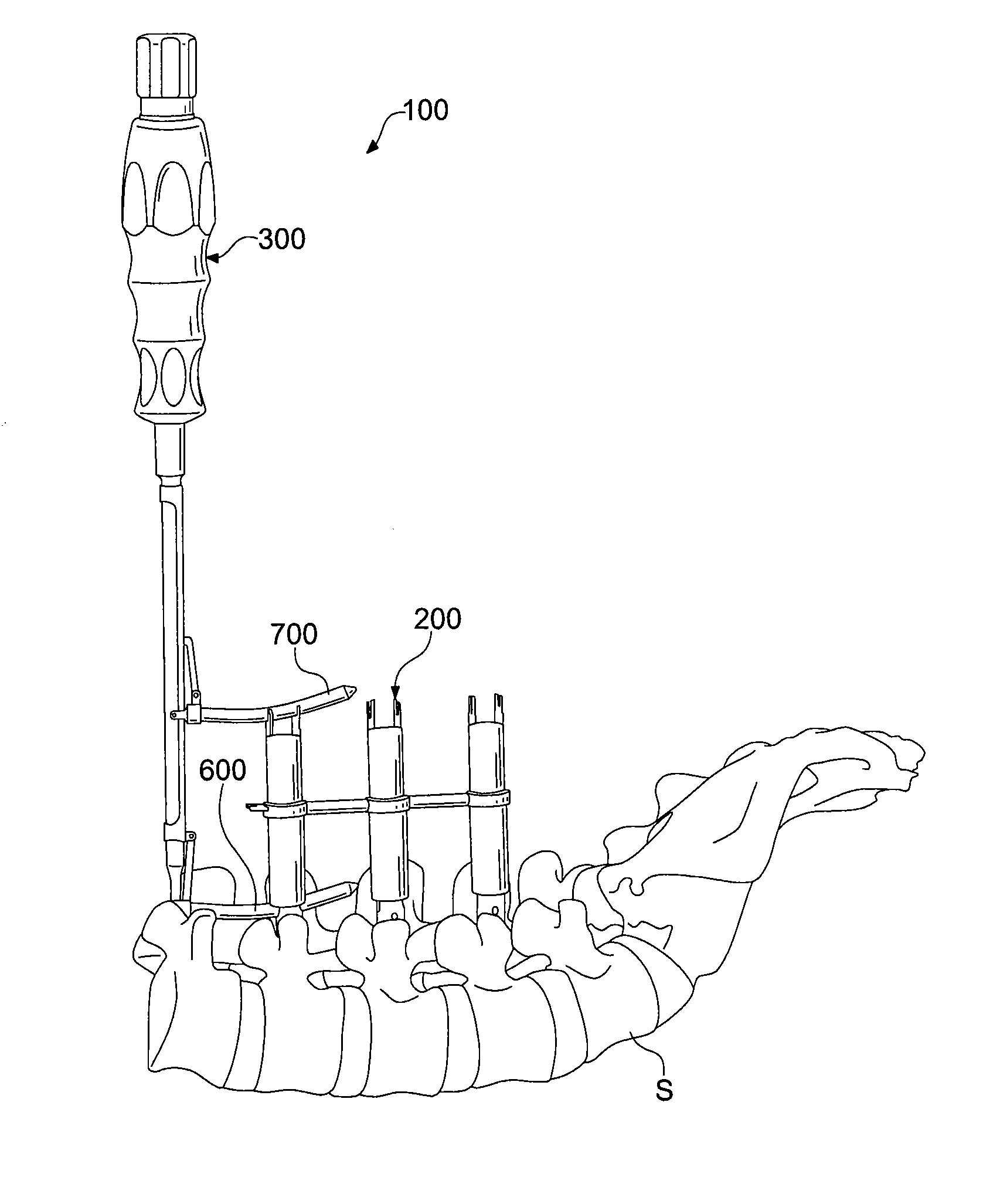
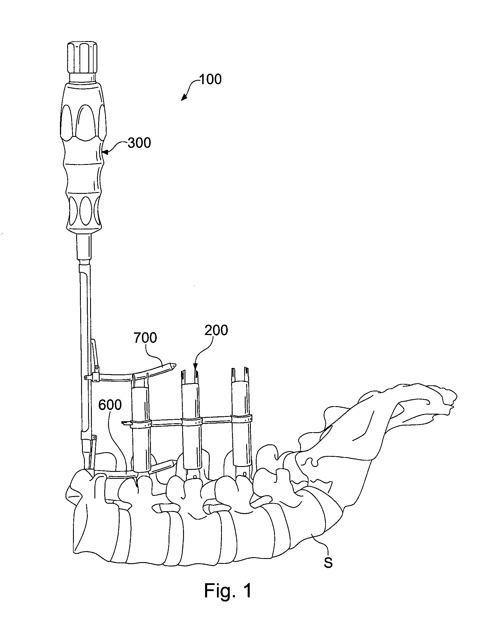
[0028]Rod insertion systems in accordance with the invention utilize visual guides that simulate the movement and relative position of a spinal fixation rod during a rod insertion procedure. While the systems can be used in various rod insertion procedures, the systems are particularly useful for percutaneous procedures and other rod insertion approaches where small incisions are made, and where the rod is being placed over two or more levels. In such cases, the implanted pedicle screws are not typically arranged in a straight line configuration. Rather, the rod receiving channels of the implants are typically offset from one another, forming a complex serpentine ...


PUM


Abstract

Instruments and methods for inserting a spinal fixation rod include various components for inserting a rod with visual guidance. One kit includes a plurality of hollow elongated extension tubes and rod templates. The tube connectors connect the extension tubes in series. Another kit includes a rod guidance instrument having a sleeve. A guide member is attachable to the midsection of the sleeve, and a spinal fixation rod is attachable to the distal end of the sleeve. A method for inserting a spinal fixation rod into a plurality of rod receiving implants includes the steps of contouring a fixation rod to conform to a predetermined shape, contouring a guide member to match the shape of the contoured rod, and guiding the fixation rod into a rod receiving implant by maneuvering the guide member through a guide slot representing the location of the rod receiving implant.

Description

FIELD OF THE INVENTION[0001]The present invention relates generally to spinal fixation, and more specifically to components and methods for inserting a spinal fixation member with visual guidance.BACKGROUND OF THE INVENTION[0002]In many spinal fixation procedures, a spinal fixation rod is connected to implants attached to two or more vertebrae. When pedicle screws are used, the spinal fixation rod can be inserted into a rod receiving component associated with each pedicle screw. Minimally invasive procedures can make rod insertion difficult, because the surgeon only makes small incisions to insert each pedicle screw. Once the pedicle screws are attached to the vertebrae, the rod receiving components are not visible beneath the incisions. Inserting a spinal fixation rod through a first pedicle screw and navigating the rod beneath tissue into a second pedicle screw is very challenging. Minimally invasive procedures, such as percutaneous procedures, are disfavored in multi-level cases ...

Claims


Application Information

Patent Timeline
Patent Type & Authority Patents(United States)
IPC IPC(8): A61B17/70
CPCA61B17/708A61B17/7083
Inventor PEUKERT, ANDREAHAAS, ALEXANDERKOVACH, MATTHEW
Owner AESCULAP IMPLANT SYST
Why Eureka
Try Eureka