Electrical switch

a technology of electric switches and switches, applied in the field of electric switches, can solve the problems of adversely affecting the serviceability of the switch, damaging influences, etc., and achieve the effects of improving the service life of the switch, reducing the risk of water or other harmful substances ingressing, and improving sealing

Active Publication Date: 2013-09-24
MARQUARDT GMBH SCHLOSSTRASSE 16 7201 RIETHEIM-WEILHEIM 1 WEST GERMANY
View PDF16 Cites 3 Cited by
  • Summary
  • Abstract
  • Description
  • Claims
  • Application Information

AI Technical Summary

Benefits of technology

[0006]The invention is based on the object of further developing an electrical switch such that protection against such ingress of harmful substances into the switch is improved.
[0007]In the switch according to the invention, the operating member comprises a moving inner part which is located in the interior of the housing, preferably an inner rocker which can pivot, and a moving outer part, which is located on the exterior of the housing, in particular an outer rocker which also can pivot. As such, the seal completely cover the opening, with the outer part moving the inner part, via the elastically moving seal while providing the switching action on the contact system. Accordingly, the invention provides a switch with improved sealing. Therefore, the invention provides a rocker switch in which an integrated sealing cap is molded on the switch housing, with the outer rocker acting on the upper part of the sealing cap, and with the inner rocker thus being moved by the lower part of the sealing cap such that the inner rocker in turn switches the contact system.
[0008]In a further embodiment, the seal may have a dome-like projection. The projection is preferably provided in the form of an elastic bellows. In this case, the projection can be moved elastically with respect to the inner part by the movement of the outer part. Furthermore, a pin on the inner part projects into the opening of the projection such that, during movement of the outer part, the projection acts on the pin in order to move the inner part. An embodiment such as this is distinguished by the improved functional reliability and a longer life of the switch.

Problems solved by technology

For example, such damaging influences may be exposure to moisture, dust or the like.
However, it has been found that harmful substances, for example water, can migrate into the interior of the housing between the plunger and the seal, and thereby adversely affect the serviceability of the switch.

Method used


Image

  • Electrical switch
  • Electrical switch
  • Electrical switch

Examples


Embodiment Construction

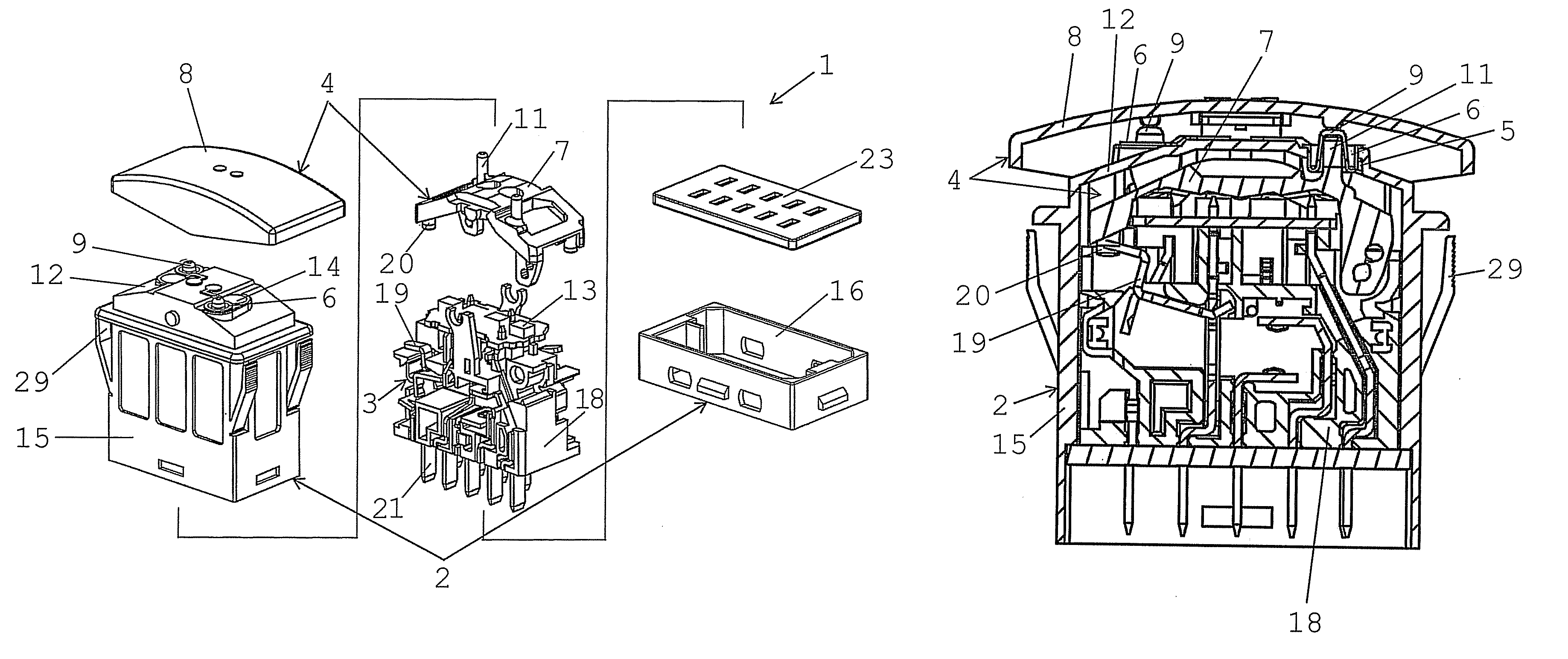
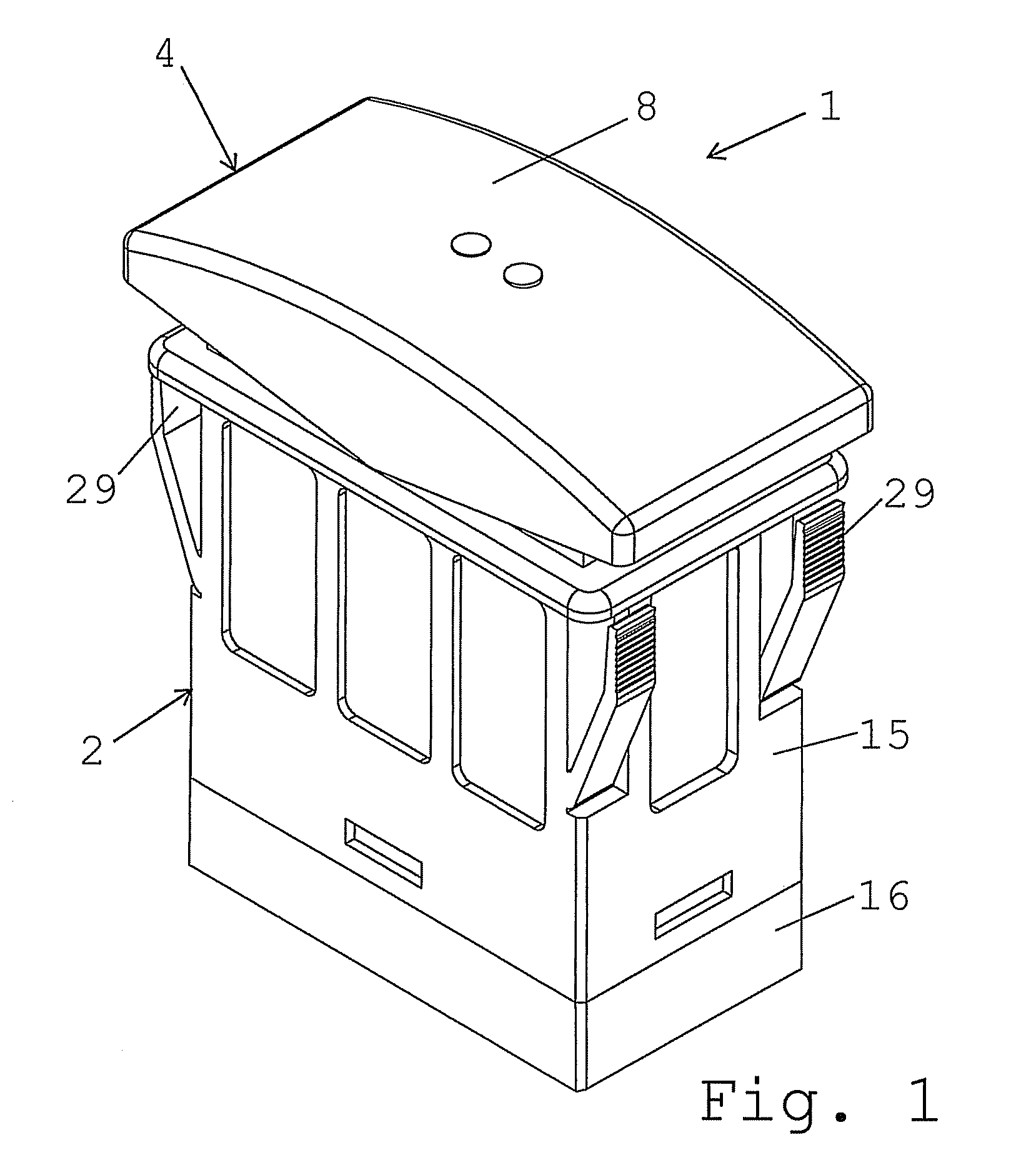
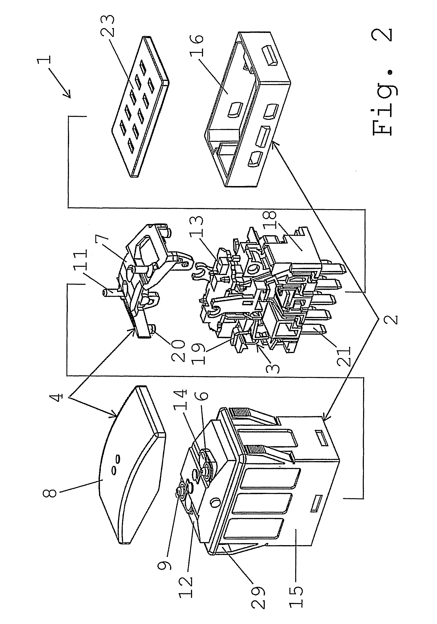
[0038]FIG. 1 shows an electrical switch 1 with a housing 2. The housing 2 can be inserted by means of latching arms 29 into a receptacle on a panel of an electrical appliance. An operating member 4, which is in the form of a rocker, is arranged on the housing 2 such that it can move, and with the aid of which the user can switch the switch 1 on and / or off. In the case of the switch 1 shown in FIG. 1, the switch is designed such that the operating member 4 is located above the panel. In another embodiment, which can be seen in FIG. 4, the operating member 4 is located below the panel and projects out of the receptacle in the panel, for operation by the user.

[0039]The individual parts of the switch 1 are shown in more detail in an exploded illustration in FIG. 2. The switch 1 has a contact system 3 which is located in the interior of the housing 2 and which is acted on for switching purposes by the operating member 4, when operated by the user. For the switching action of the operatin...


PUM


Abstract

An electrical switch having a housing, with a contact system being located in the interior of the housing. A movable operating member, in particular in the form of a rocker, is arranged on the housing for switching action on the contact system. An opening is located in the housing, for the switching action of the operating member. An elastic seal for the opening is attached to the housing. The operating member comprises a moving inner part, which is located in the interior of the housing, in particular an inner rocker which can pivot, and a moving outer part, which is located on the exterior of the housing, in particular an outer rocker which can pivot. The seal completely covers the opening. The outer part moves the inner part, via the elastically moving seal, for switching action on the contact system.

Description

CROSS REFERENCE TO RELATED APPLICATION[0001]This application claims the benefit under 35 USC §119(e) of U.S. Provisional Application Ser. No. 61 / 245,311, having a filing date of Sep. 24, 2009, the entirety of which is incorporated herein by reference.FIELD OF THE INVENTION[0002]The invention relates to an electrical switch.BACKGROUND OF THE INVENTION[0003]In the case of electrical appliances which are used in severe operating conditions, precautions must be taken to ensure that the electrical switch is protected against damaging influences which may adversely affect its serviceability. For example, such damaging influences may be exposure to moisture, dust or the like. This applies particularly to switches which are used in appliances for building technology, agriculture, building trade, or the like.[0004]One such electrical switch is known from DE 197 05 068 A1. The switch has a housing with a contact system which is located in the interior of the housing. The operating member is i...

Claims


Application Information

Patent Timeline
Patent Type & Authority Patents(United States)
IPC IPC(8): H01H19/06
CPCH01H23/06
Inventor LIMBERT, EDWARD
Owner MARQUARDT GMBH SCHLOSSTRASSE 16 7201 RIETHEIM-WEILHEIM 1 WEST GERMANY
Why Eureka
Try Eureka