Burner for premix-type combustion

a combustion chamber and burner technology, applied in combustion types, ignition of turbine/propulsion engines, lighting and heating apparatuses, etc., can solve the problem of not getting the optimal nitrogen emission value, and achieve the effect of stable combustion, reducing aerodynamic losses and the necessary pressure, and improving step

Inactive Publication Date: 2011-07-12
ANSALDO ENERGIA SWITZERLAND AG
View PDF14 Cites 3 Cited by
  • Summary
  • Abstract
  • Description
  • Claims
  • Application Information

AI Technical Summary

Benefits of technology

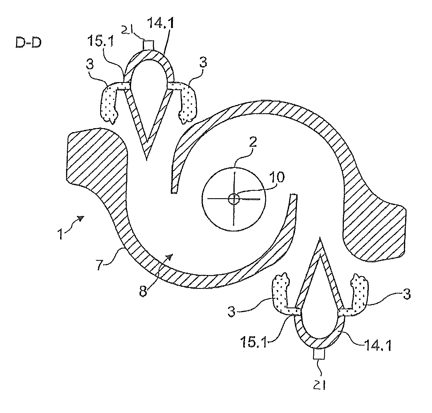
[0008]It is an object of the present invention to propose a burner for premix-type combustion and a method for operating a burner which make possible stable premix-type combustion with as homogeneous as possible a mixing of the premix fuel with the combustion air and with reduced harmful substance emission.

Problems solved by technology

As the injection takes place from one side of the air inlet slot and homogeneous mixing of the premix fuel with the combustion air over the entire width of the air inlet slot is thus not achieved, optimum nitrogen emission values are not obtained.

Method used


Image

  • Burner for premix-type combustion
  • Burner for premix-type combustion
  • Burner for premix-type combustion

Examples


Embodiment Construction

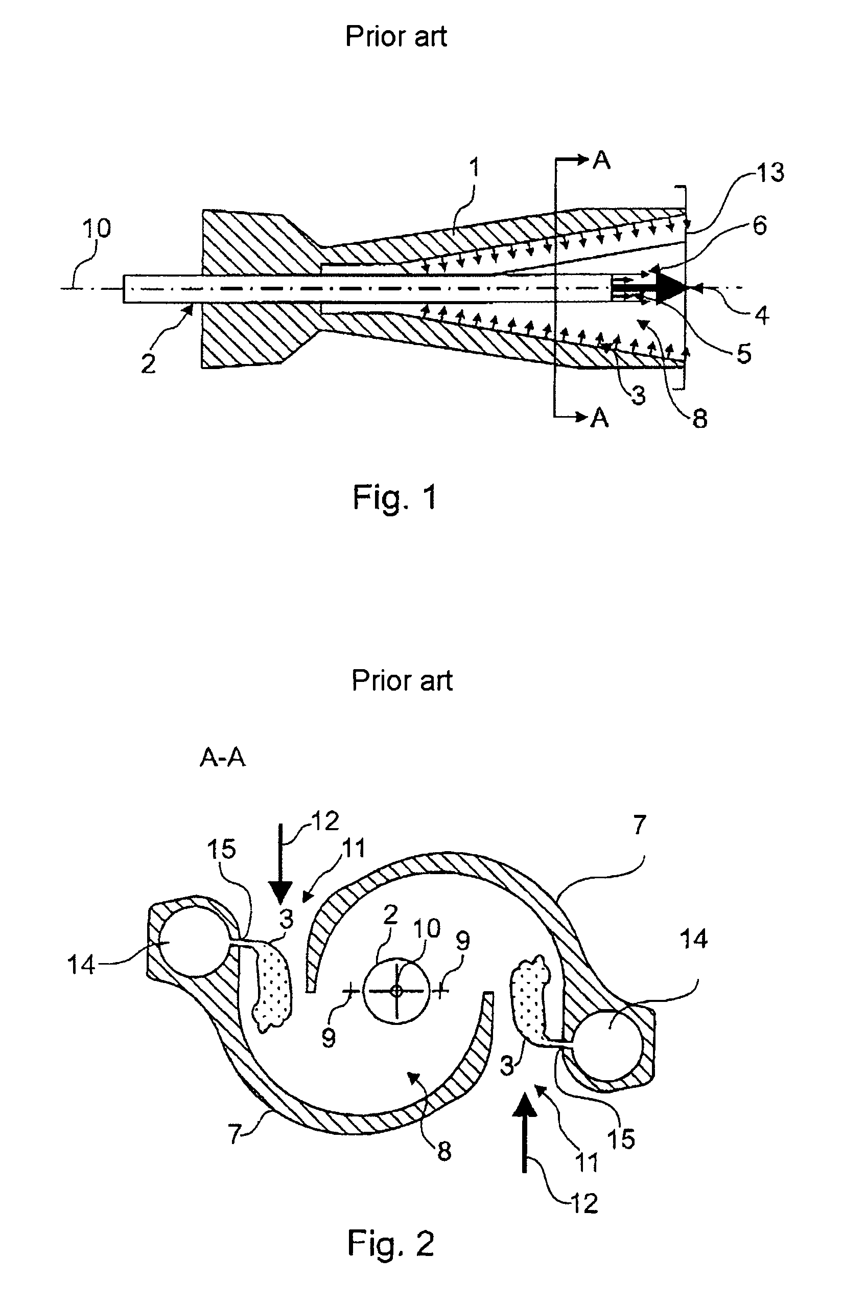
[0044]FIG. 1 shows a longitudinal cross section of a conical burner 1 according to the prior art, as described in EP 0 321 809 A1, for example. In this connection, FIG. 2 shows a cross section along the line A-A of the burner illustrated in FIG. 1. Reference is made below to the numbers of both FIG. 1 and FIG. 2.

[0045]The cone cavity 8 of the burner 1 is formed by two part cone bodies 7 which are displaced radially in relation to one another. The displacement of the longitudinal axes of symmetry 9 of the part cone bodies 7 forms tangential air inlet slots 11, through which the combustion air 12 mixed with premix fuel 3 flows into the cone cavity 8. The burner axis 10 lies centrally and on a line between the longitudinal axes of symmetry 9 of the part cone bodies 7. A jet pipe 2 is provided in the region of this burner axis 10 in order to inject liquid fuel 4 into the combustion space 8. In addition, pilot fuel 6 is introduced into the cone cavity, for initiating or stabilizing the c...


PUM


Abstract

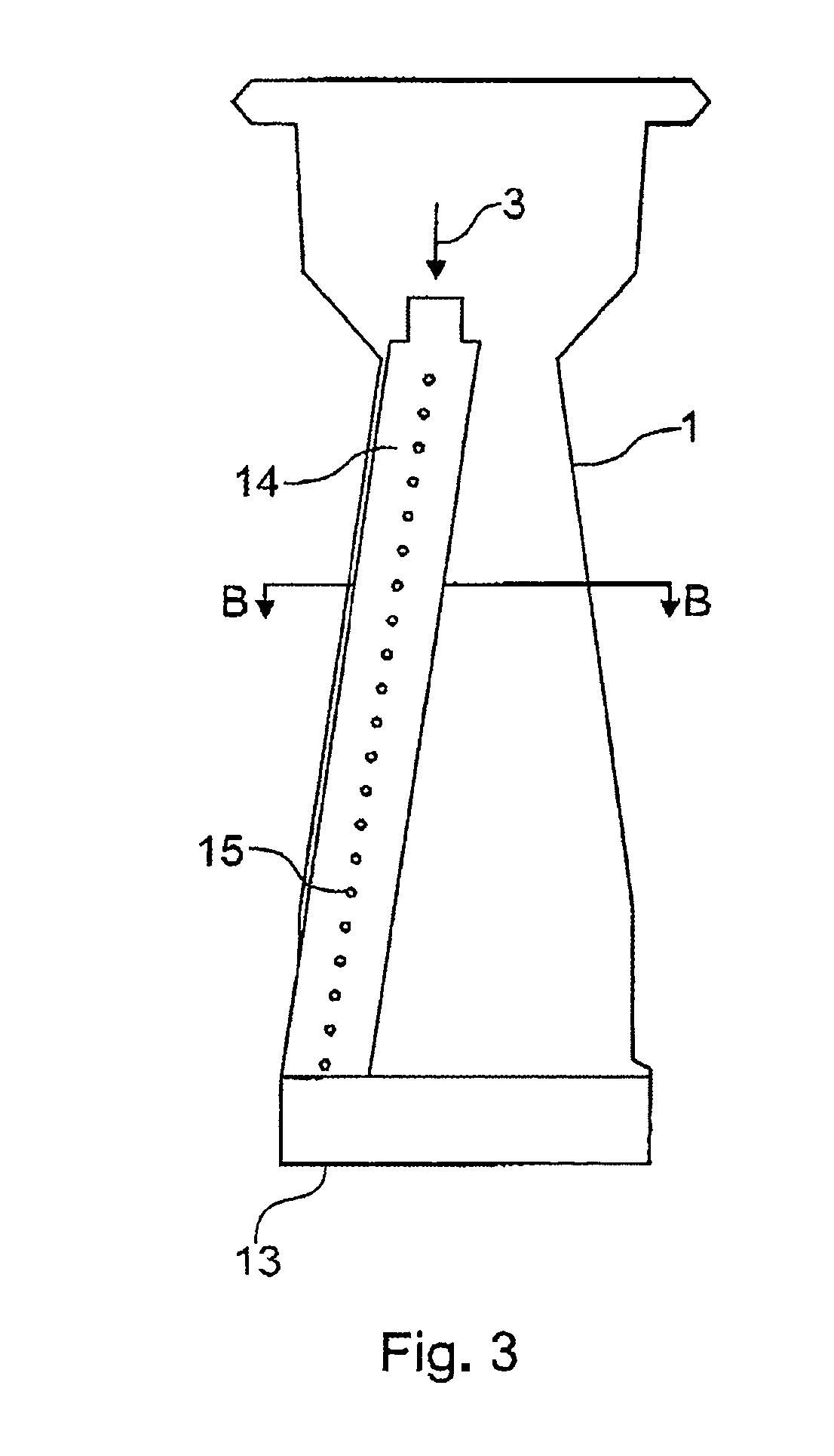
The invention relates to a burner for premix-type combustion having a cavity which has at least one tangential air inlet slot for the supply of a combustion air flow, a device for the injection of fuel into the cavity which is provided in the region of a burner axis, and a device for the injection of premix fuel into the air inlet slots which is provided centrally in the inflow region of the combustion air flow. The device for the injection of premix fuel into the air inlet slots has at least one fuel supply, the fuel outlet openings of which are arranged in such a way that the premix fuel is introduced into the combustion air flow on both sides of the at least one fuel supply related to a cross-sectional plane at right angles to the burner axis.

Description

[0001]This application is based on and claims priority to Swiss Application No. 01031 / 05, filed on Jun. 17, 2005 designating the U.S., the entire content of which is hereby incorporated by reference.TECHNICAL FIELD[0002]The invention relates to a burner for premix-type combustion according to claim 1 and a method for operating a burner according to claim 23.PRIOR ART[0003]In view of increasingly strict regulations on the emission of harmful substances, great efforts are being made to produce burners with low emission of harmful substances, in particular nitrogen oxides. In this connection, a preferred arrangement is burners in the form of conical hollow bodies which have tangential air inlet slots. Combustion air flows through the air inlet slots into the conical burner cavity. Fuel, in particular gaseous fuel, is supplied to the combustion air flow via fuel outlet openings at the edges of the air inlet slots. Moreover, liquid fuel is introduced, in particular sprayed, into the coni...

Claims


Application Information

Patent Timeline
Patent Type & Authority Patents(United States)
IPC IPC(8): F02C1/00
CPCF23C7/002F23D11/402F23D17/002F23R3/286F23C2900/07002
Inventor EROGLU, ADNANTOQAN, MAJED
Owner ANSALDO ENERGIA SWITZERLAND AG
Why Eureka
Try Eureka