Exhaust system and method for operating the same

a technology of exhaust system and exhaust gas, which is applied in the direction of exhaust gas recirculation, exhaust treatment, and non-fuel substance addition to fuel, etc. it can solve the problems of affecting the operation of the exhaust system. , to achieve the effect of simple construction

Inactive Publication Date: 2006-11-09
EMITEC GESELLSCHAFT FUR EMISSIONSTECHNOLOGIE MBH
View PDF20 Cites 4 Cited by
  • Summary
  • Abstract
  • Description
  • Claims
  • Application Information

AI Technical Summary

Benefits of technology

[0007] It is accordingly an object of the invention to provide an exhaust system for a mobile combustion engine and a method for operating the same, which overcome the hereinafore-mentioned disadvantages of the heretofore-known devices and methods of this general type and in which the exhaust system has a simple construction and is inexpensive and the method for operating the exhaust system ensures functional reliability of components in the exhaust system.
[0013] In accordance with an additional feature of the invention, it is particularly advantageous if the honeycomb body has a plurality of at least partly structured sheet metal layers, which are stacked and / or coiled in such a way that passages through which the exhaust gas can flow are formed. The use of layers of metal sheet to produce honeycomb bodies has the advantage that they can be produced with particularly thin walls. For example, sheet metal layers with a thickness of from 12 to 50 μm can be used, achieving passage densities over the cross-sectional area of the honeycomb structure, which lie in the range from 200 to 800 cpsi (cells per square inch). The structured sheet metal layers preferably form passages which are disposed substantially parallel to one another. It is possible under some circumstances for microstructures to be provided to create turbulence, openings for gas exchange into adjacent passages and varying thicknesses of the sheet metal layers.
[0019] This ensures that components of the exhaust system, which have a tendency to suffer coking, such as for example throttle valves, valves, etc, function satisfactorily over a long period of time. This leads to particularly easy servicing and great effectiveness of the exhaust system.
[0020] In accordance with another mode of the invention, the exhaust gas that is at least partly cracked in the reaction chamber is fed to an exhaust-gas recirculation system, which returns a partial stream of exhaust gas to a combustion engine. This has the advantage that in turn only short-chain hydrocarbons are provided for the combustion engine, and the latter can carry out a combustion that is effective and produces few harmful substances.
[0022] In accordance with an added mode of the invention, in particular, in the case of such a procedure, it is advantageous that at least 50%, in particular at least 80%, of the long-chain hydrocarbons contained in the exhaust gas are cracked in the at least one reaction chamber, with normal pressure preferably prevailing in the reaction chamber. This has the consequence on one hand that the reaction chamber itself generally does not become gummed up, and consequently only has to be checked at very infrequent servicing intervals, but on the other hand the coking of downstream components is also prevented.

Problems solved by technology

As extensive investigations of various components of the exhaust system have shown, one of the causes of the aforementioned problems can be seen in the tacky, wax-like coking deposits which accumulate in particular in the region of small gaps or interstices.
Moving parts such as throttle valves or valves are particularly at risk therefrom.
The accumulation of the coking deposits in the region of the lifting or rotating path of the throttle valves and valves has the effect that they are restricted in their freedom of movement.
The coking is often caused by long-chain hydrocarbons, which in this region initially form an agglomerate and subsequently lead for example to the sticking of moving parts.

Method used


Image

  • Exhaust system and method for operating the same
  • Exhaust system and method for operating the same
  • Exhaust system and method for operating the same

Examples


Embodiment Construction

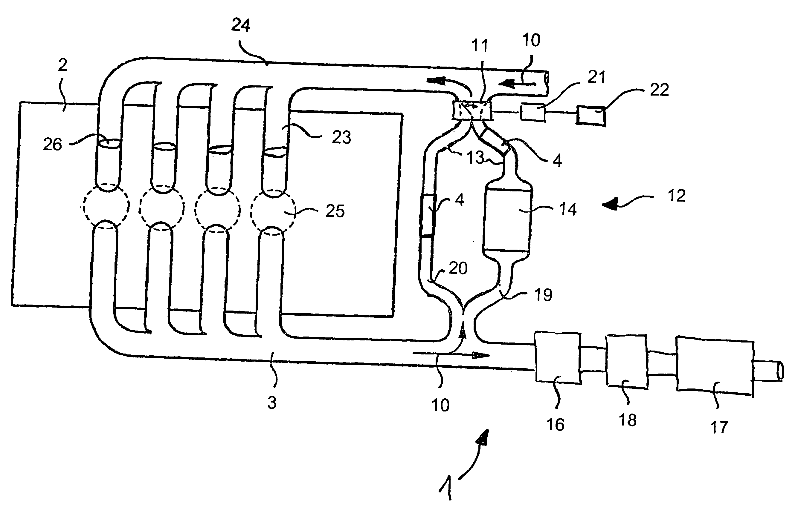
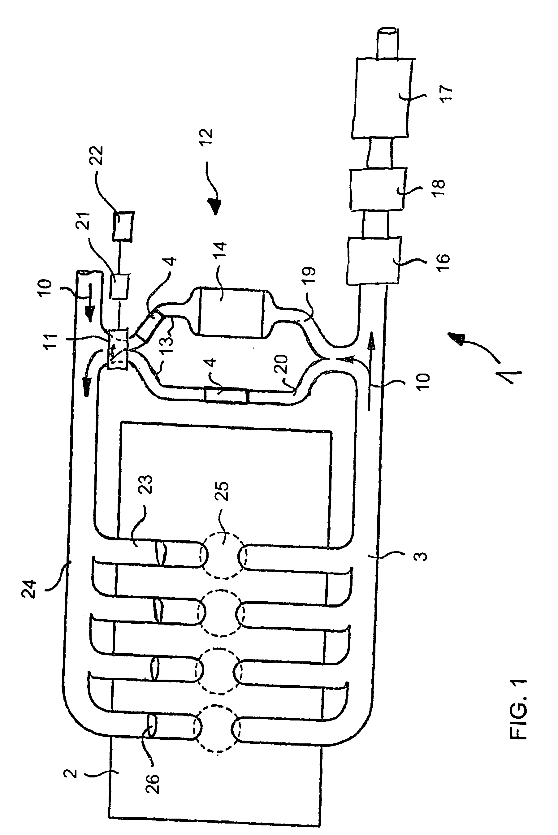
[0030] Referring now to the figures of the drawings in detail and first, particularly, to FIG. 1 thereof, there is seen a diagrammatic view of a structure of an exhaust system 1 with an exhaust-gas recirculation system 12 and a combustion engine 2. The exhaust-gas recirculation system 12 is formed with two lines, that is to say it includes a first line 19 and a second line 20. An exhaust-gas cooler 14 is disposed in the first line 19, bringing about cooling of a partial stream of exhaust gas flowing through it, in particular at high temperatures of the exhaust gas. Regulation of a direction of flow 10 in the exhaust-gas recirculation system 12 takes place through the use of a valve 11, which is preferably configured as a rotating double valve. A drive 21 of the valve 11 is connected to a control unit 22, so that pre-determinable partial streams of exhaust gas can be produced.

[0031] In principle, a fuel-air mixture is fed to the combustion engine 2 through an air-intake pipe 24 and ...


PUM


Abstract

An exhaust system for a mobile combustion engine includes at least one exhaust pipe. The exhaust pipe has at least one catalytically active reaction chamber, inside which long-chain hydrocarbons contained in the exhaust gas are cracked. A method for operating such an exhaust system is also provided.

Description

CROSS-REFERENCE TO RELATED APPLICATION [0001] This application is a continuing application, under 35 U.S.C. § 120, of copending International Application No. PCT / EP2002 / 012472, filed Nov. 8, 2002, which designated the United States.BACKGROUND OF THE INVENTION Field of the Invention [0002] The present invention relates to an exhaust system of a mobile combustion engine or mobile internal combustion engine and to a method for operating the same. The exhaust system is understood in principle as meaning all types of exhaust systems, for example for spark-ignition engines, diesel engines and other types of engines in which a fuel containing carbon is burned. [0003] Hydrocarbon mixtures are produced and consumed in large quantities. Hydrocarbon is the name given to an organic compound, which includes only the elements carbon and water. Short-chain hydrocarbons with up to four carbon atoms are gaseous at room temperature. The hydrocarbons from pentane (C5) are liquid at room temperature. L...

Claims


Application Information

Patent Timeline
Patent Type & Authority Applications(United States)
IPC IPC(8): F02M25/06F01N3/10B01D53/94F01N3/021F01N3/08F01N3/20F01N3/28F01N13/02F02M25/07
CPCB01D53/944F01N13/009F01N3/0842F01N3/10F01N3/20F01N3/281F01N3/2882F01N2330/02F01N2370/04F02M25/0724F02M25/0728F02M25/074F02M25/0796Y02T10/121F01N3/021F02M26/21F02M26/25F02M26/35F02M26/71F01N3/28
Inventor NAGEL, THOMASBERGMANN, ANDREE
Owner EMITEC GESELLSCHAFT FUR EMISSIONSTECHNOLOGIE MBH
Why Eureka
Try Eureka