
Medical image display apparatus and method, and program for displaying medical image

a medical image and display apparatus technology, applied in the field of medical image display apparatus and medical image display method, and a program for displaying medical images, can solve the problems of poor visibility of medical image or accessory information, medical errors, and difficulty in comparing medical image with past medical images, so as to reduce the visibility of medical images and improve visibility.

Inactive Publication Date: 2013-09-24
FUJIFILM CORP
View PDF7 Cites 4 Cited by
  • Summary
  • Abstract
  • Description
  • Claims
  • Application Information

AI Technical Summary

Benefits of technology

The patent is about a way to display extra information about a medical image without making it hard to see the image. This is done by making important information display in a way that is easy to see, while omitting or displaying less important information in a different way to prevent it from getting in the way. This way, the medical image is always visible and can be used for diagnosis and treatment purposes without being obscured.

Problems solved by technology

In the overlapped part, visibility of the medical image or the accessory information gets worse.
This may lead to medical errors such as a misdiagnosis and the oversight of a lesion.
Beside that, the shifted display section of the medical image or the accessory information from its normal position makes it difficult to compare the medical image with past medical images.
The third embodiment of the prior art requires the interpreting doctor to designate the region of interest, which is inconvenient and troublesome.
Concerning the medical image to be subjected to the radiological interpretation, however, the size reduction causes the problem that the image deterioration decreases the accuracy of the diagnosis.

Method used


Image

  • Medical image display apparatus and method, and program for displaying medical image
  • Medical image display apparatus and method, and program for displaying medical image
  • Medical image display apparatus and method, and program for displaying medical image

Examples


first embodiment

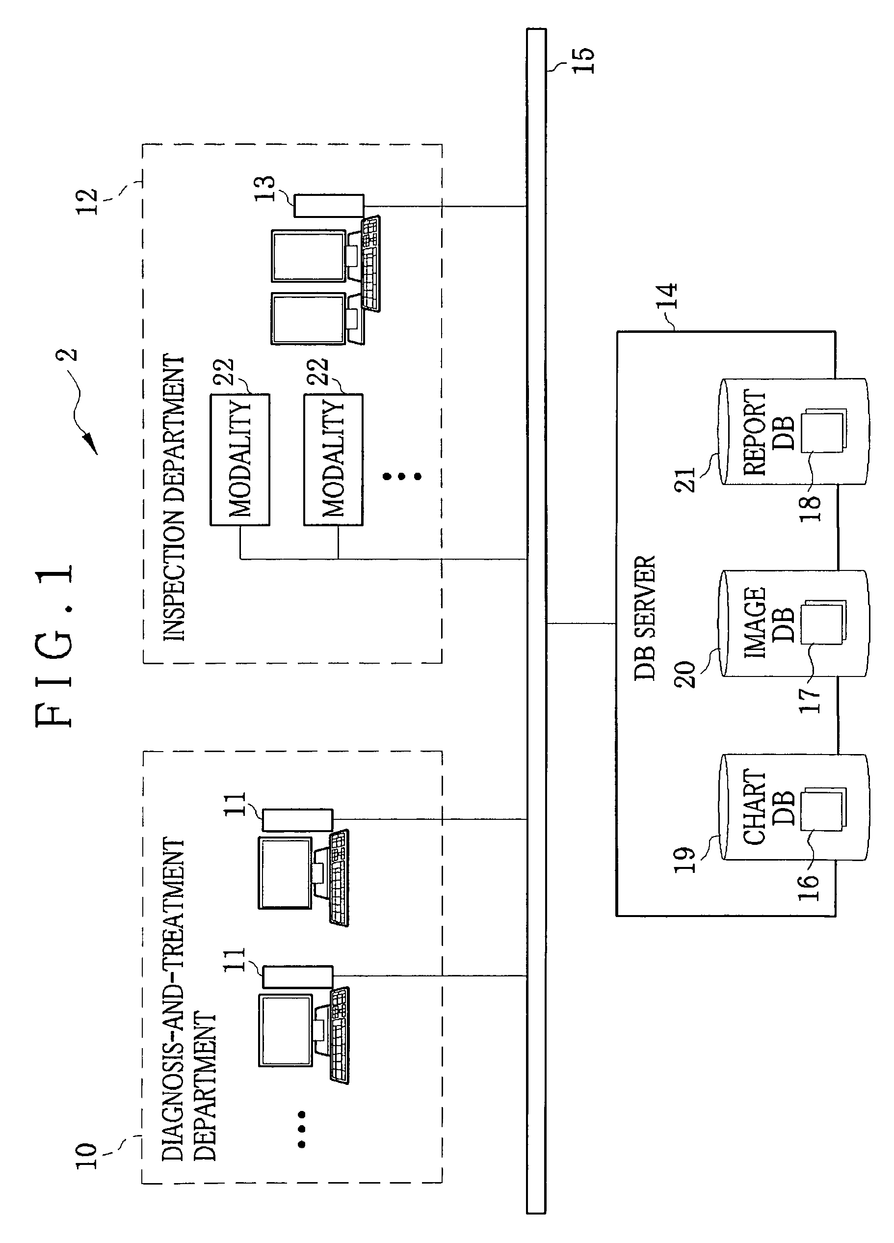
[0047]In FIG. 1, a medical information system is constructed in a medical facility such as hospital, and comprises diagnosis-and-treatment department terminals 11 arranged in diagnosis-and-treatment departments 10, a report producing terminal 13 arranged in a radiological inspection department, hereinafter called simply as the inspection department 12, and a database (DB) server 14, which are all connected to a network 15 to communicate with each other. The network 15 is for example a LAN (Local Area Network) in a hospital.

[0048]The diagnosis-and-treatment department terminals 11 are operated by doctors in the diagnosis-and-treatment departments 10, to browse and input data on patients' records called charts 16 or issue orders for inspections to the inspection department 12. The diagnosis-and-treatment department terminal 11 also displays medical images 17 as obtained through an inspection as well as reports 18 on the result of the inspection, which are submitted from the inspection...

second embodiment

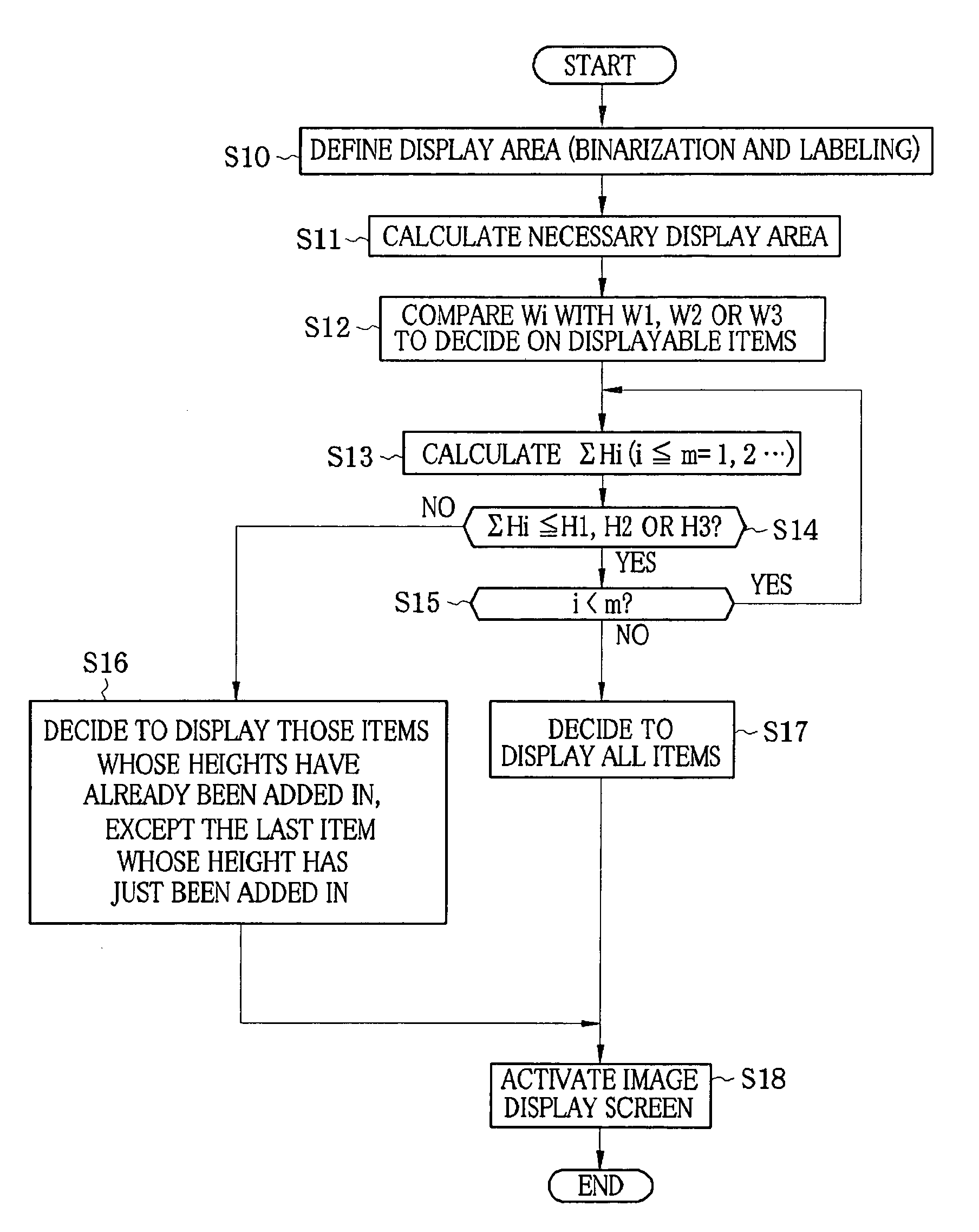
[0122]In the second embodiment shown in FIG. 9, an image display screen 46 is provided with a transparent display frame 80, which is illustrated as an area hatched by chain-dotted lines. The transparent display frame 80 is an extension from the bottom of a first section 62 of an accessory information display area, whose size and position are defined by an area defining section 42. So the transparent display frame 80 overlaps an upper fragment of a main subject display area 60. The transparent display frame 80 is for example displaying those items which are decided to be omitted from the first section 62 as a result of the above-described calculation and comparison of the sum ΣHi with the height H1 of the first section 62. The items are displayed transparently in the transparent display frame 80, so that they will not hinder the visibility of the main subject display area 60. A console controller 40 controls the degree of transparency of the displayed items in the transparent display...

third embodiment

[0127]According to the third embodiment shown in FIG. 10, a first display section 62 is provided with a scroll display frame 81. The scroll display frame 81 displays those items which are decided not to be displayed in the regular style. The decision about which item is to be displayed in the regular style may be made through the same processes as described with respect to the first embodiment: comparison between the width Wi of the necessary display area of each item and the width W1, W2 or W3 of an applied display section 62, 63 or 64, as well as comparison between the sum ΣHi of the heights Hi of the necessary display areas and the height H1, H2 or H3 of the applied display section. Then, those items which are refused from being displayed in the regular style are displayed in the scroll display frame 81, being scrolled continuously in a horizontal direction. Under the control of a console controller 40, the scrolling speed of the scroll display frame 81 is set at such a level tha...


PUM


Abstract

A storage device of a report producing terminal stores an importance table. The importance table stores grades of importance of respective items of accessory information on medical images. Prior to displaying a medical image on a screen, an area defining section extracts a main subject display area of the medical image, and defines an accessory information display area outside the main subject display area. A display style defining section calculates a necessary display area for each individual item of the accessory information, and discriminates between those items which fit in the accessory information display area and those which do not. The display style defining section decides not to display the items which do not fit in the accessory information display area, or decides to display them in a transparent style, in a scrolling style, in a switching style or with a small font.

Description

CROSS-REFERENCE TO RELATED APPLICATIONS[0001]The present application claims priority from Japanese Patent Application No. 2008-223081, filed Sep. 1, 2008, the contents of which are herein incorporated by reference in their entirety.FIELD OF THE INVENTION[0002]The present invention relates to a medical image display apparatus and a medical image display method, and a program for displaying a medical image, which permit displaying a medical image and its accessory information overlapped with each other on a screen of a display device.BACKGROUND OF THE INVENTION[0003]Medical practices have recently been introducing various computer systems that deal with medical documents such as medical reports, hereinafter called simply as the reports, in the form of electronic data to facilitate making and managing the medical documents. Among those computer systems for medical use, a report maker assistant system that facilitates making the report is widely used in practice.[0004]The report maker a...

Claims


Application Information

Patent Timeline
Patent Type & Authority Patents(United States)
IPC IPC(8): G09G5/00
CPCG06F19/321G16H30/20G16H30/40G16H15/00
Inventor ISHIDA, HIRONOBUMURAYAMA, MASASHISUGIHARA, KEIJI
Owner FUJIFILM CORP
Learn More