Roll stand

a technology of rolling stand and rolling plate, which is applied in the direction of metal rolling arrangement, counter-pressure device, manufacturing tools, etc., can solve the problems of large or small deviation of roll gap shape, deviation in flatness, and general insufficient compensating for various deflection states, so as to achieve a simple and less costly manner, the effect of eliminating costly mechanisms

Inactive Publication Date: 2013-10-01
SMS DEMAG AG
View PDF15 Cites 2 Cited by
  • Summary
  • Abstract
  • Description
  • Claims
  • Application Information

AI Technical Summary

Benefits of technology

[0011]The object of this invention is to further develop a roll stand of the type described above so as to enable a bending moment counteracting the roll bending moment to be introduced into the roll in a simpler and less costly manner and using as few elements as possible. The goal is thus to be able to eliminate costly mechanisms, while at the same time ensuring that abnormal deflections of the roll resulting from the roll forces can be compensated as well as possible.SUMMARY OF THE INVENTION
[0019]The proposed solution is thus aimed at largely preventing the rolling-force-induced deflections of the roll stand, and the associated imperfections in the roll gap shape, by an approach such that bending moments are built up on the rolls (in particular, the backup rolls and work rolls) by the rolling force itself, the bending effect of which is opposed to the rolling-force-induced deflection of the rolls.
[0020]This invention is thus based on a basic stand that prevents the unwanted roll-force-induced roll deformations to a large extent and essentially independently of the rolling force, and thus has the potential to succeed with a minimum amount of active flatness-control systems.

Problems solved by technology

One of the classical problems in rolling flat steel is thus the roll-force-induced deflection of the set of rolls, which problem results in a greater or lesser deviation of the roll gap shape from the ideal form determined by the strip profile, and thus in deviations in flatness.
The effect, however, is generally not sufficient to compensate for the various deflection states in a rolling mill due to varying rigidity and width of the workpiece.
The use of variably crowned rolls is cumbersome.
Displacement systems are also expensive, and, particularly in response to load displacement, result in unwanted twisting of the stand.
The previously known solutions are accordingly expensive and in part difficult in terms of implementation.

Method used


Image

  • Roll stand
  • Roll stand
  • Roll stand

Examples


Embodiment Construction

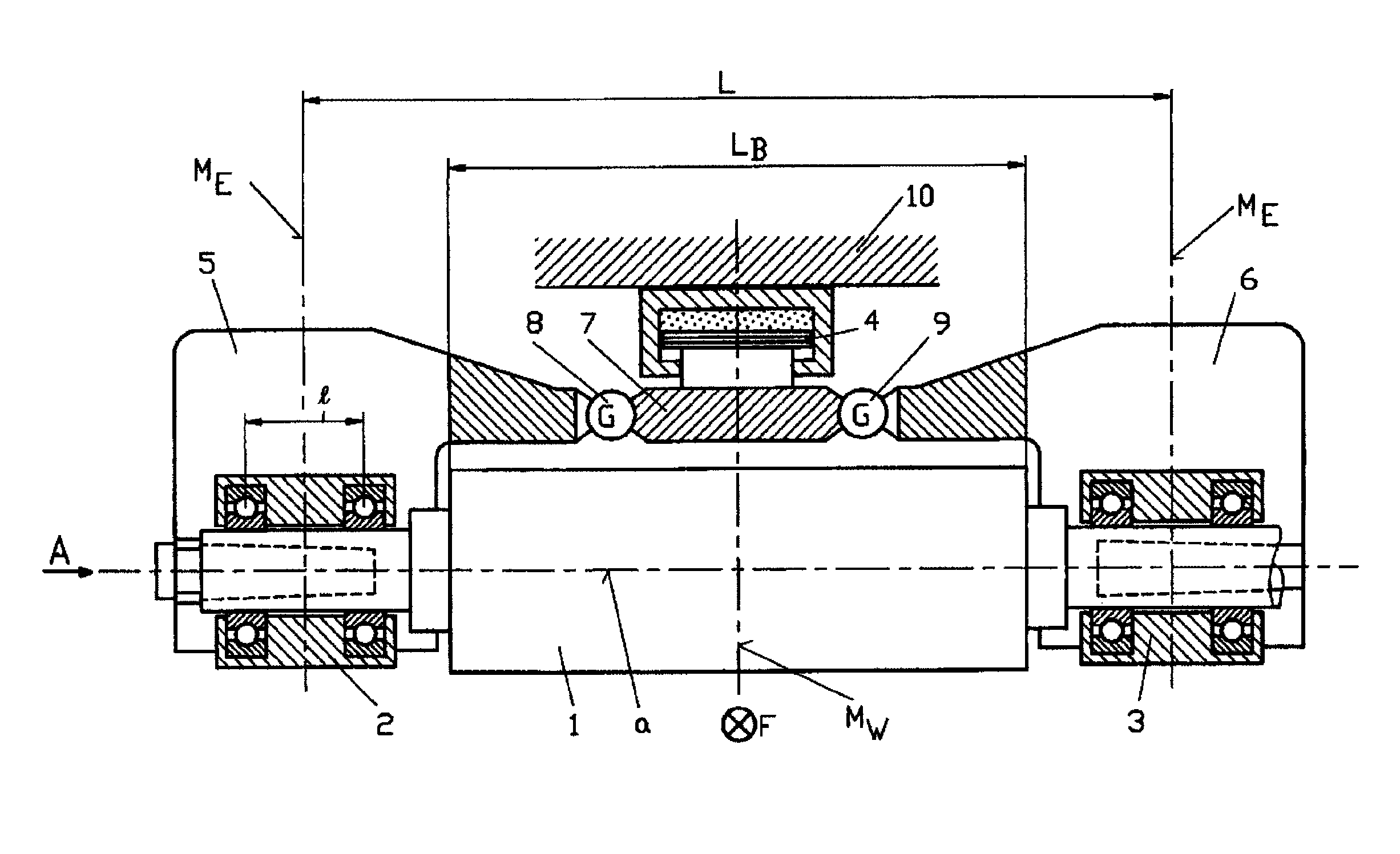
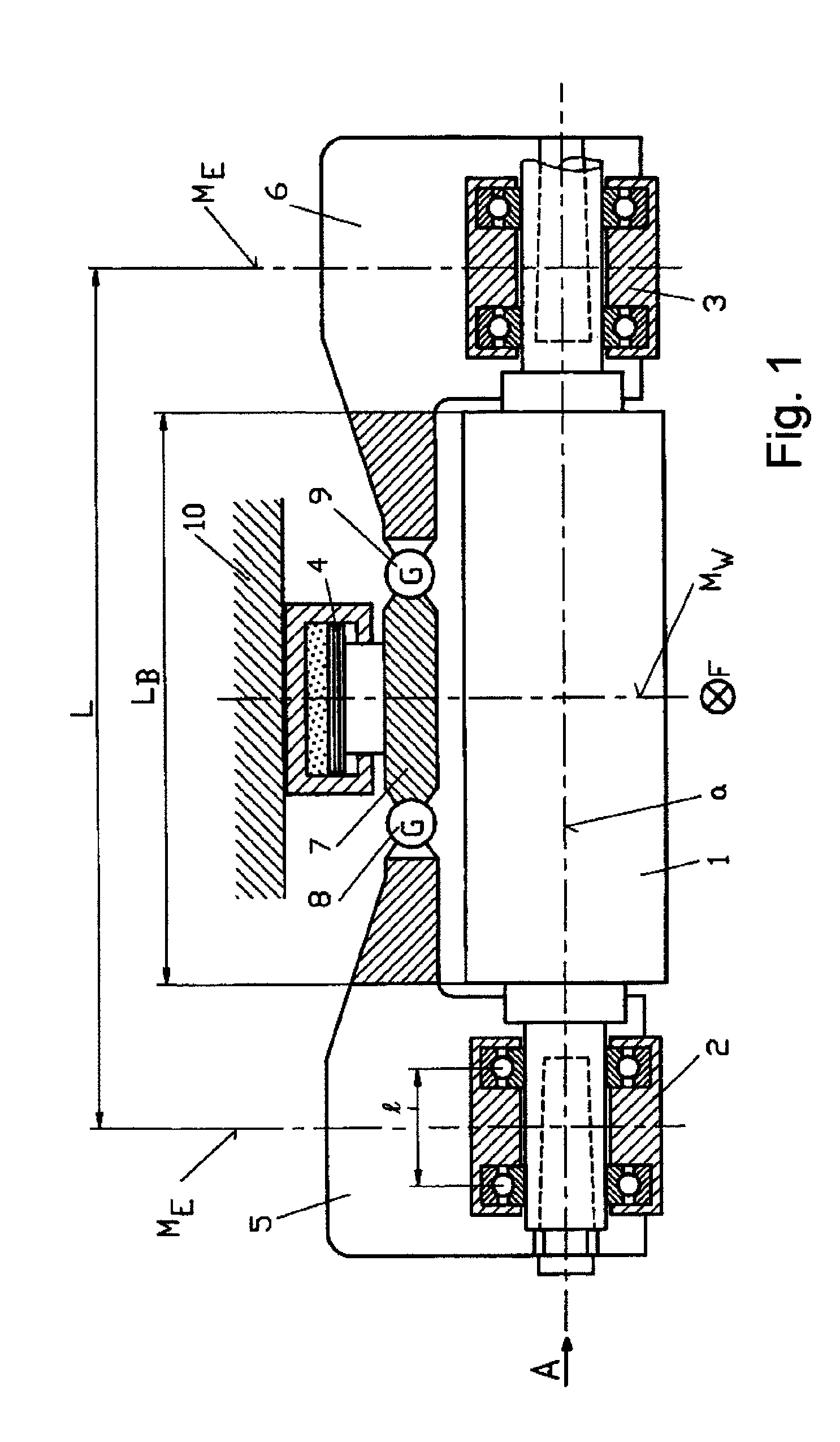
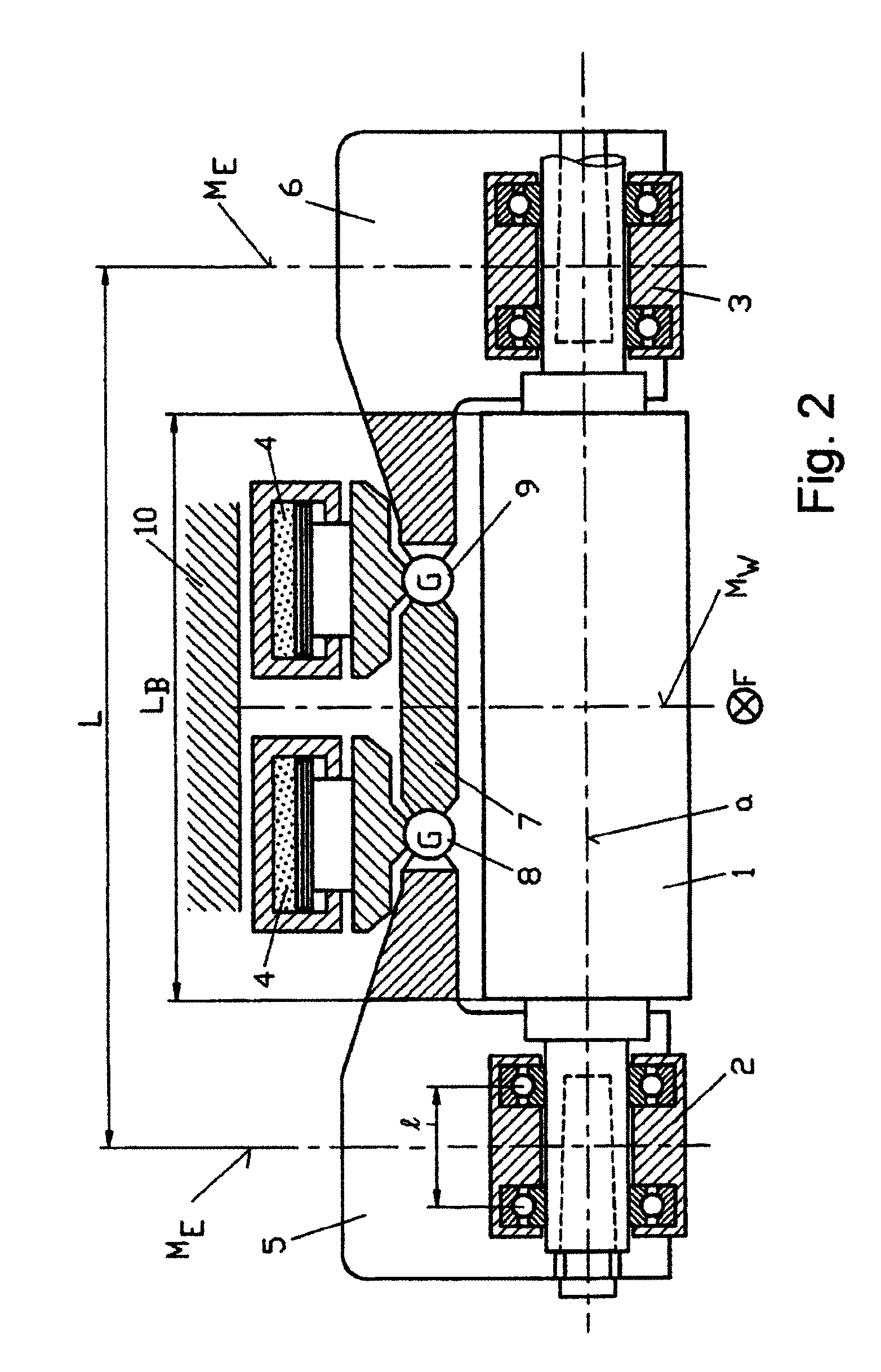
[0028]FIG. 1 shows a section of a roll stand that has a work roll 1 having one rotation axis a that is supported in the standard manner in two chocks 2 and 3. The work roll 1 rolls a workpiece, not shown, that is rolled as shown in FIG. 3 in a travel direction F (perpendicular to the plane of projection). The work roll 1 is pressed by means of a hydraulic actuator 4 against the workpiece. Due to the contact with the workpiece, a counter-bending moment is superimposed on the deflection of the roll 1, which moment is generated by two bending levers 5 and 6. The two bending levers 5, 6 are attached to the chocks 2, 3 in a torsionally rigid manner. In the center region of the apparatus, they are connected at two pivots G by means of two joints 8 and 9 to a traverse 7 on which the actuator 4 acts. The actuator 4 rests on a cross beam 10 of the roll stand.

[0029]The roll length is denoted by LB and is smaller than the spacing L of the center planes ME of the two chocks 2, 3. Also provided ...


PUM

PropertyMeasurementUnit
torqueaaaaaaaaaa
pressureaaaaaaaaaa
forcesaaaaaaaaaa

Abstract

The invention relates to a roll stand comprising at least one roll (1) having a rotation axis (a), said roll being supported in two installed parts (2, 3) disposed in the axial end regions of the roll (1) and each having a center plane (M), wherein the roll (1) can be positioned in the direction perpendicular to the transport direction (F) of the product to be rolled by means of at least one positioning element (4). In order to be able to introduce a bending moment acting counter to the roll bending moment into the roller in a simple manner and without additional elements, according to the invention, each installed part (2, 3) is connected to a bending lever (5, 6) and the positioning element (4) is disposed such that the positioning force thereof is introduced into the bending lever (5, 6) at a location (G) removed from the center plane (M) of the installed part (2, 3), and thereby into the installed part (2, 3).

Description

CROSS REFERENCE TO RELATED APPLICATIONS[0001]This application is the US national phase of PCT application PCT / EP2009 / 001911, filed 16 Mar. 2009, published 1 Oct. 2009 as WO 2009 / 118,117, and claiming the priority of German patent application 102008015826.7 itself filed 27 Mar. 2008, whose entire disclosures are herewith incorporated by reference.FIELD OF THE INVENTION[0002]The invention relates to a roll stand comprising a roll having a rotation axis and mounted in two chocks that are provided at the axial ends of the roll and that each have a center plane, the roll along with at least one actuator element being shiftable in a direction perpendicular to the travel direction of the workpiece.BACKGROUND OF THE INVENTION[0003]In the process of rolling a metallic workpiece, critical importance is attached to the most precise possible adjustment and maintenance of the roll gap since the final shape of the workpiece is determined thereby. At the same time, the rolling forces deflect the r...

Claims


Application Information

Patent Timeline
Patent Type & Authority Patents(United States)
IPC IPC(8): B21B31/00B21B31/32B21B29/00B21B13/14B21B31/07
CPCB21B29/00B21B31/32B21B13/14B21B31/16
Inventor HARTUNG, HANS-GEORG
Owner SMS DEMAG AG
Why Eureka
Try Eureka