Detachable fastening system between a male piece and a female piece, pin and female piece

a technology of detachable fastening and pin, which is applied in the direction of drags, agriculture tools and machines, construction, etc., can solve the problems of pin and tooth being lost, internal wear and breakage of pins, and pins being subjected to wear and breakage, so as to facilitate access to the upper end of pins

Active Publication Date: 2013-10-15
METALOGENIA SA
View PDF33 Cites 21 Cited by
  • Summary
  • Abstract
  • Description
  • Claims
  • Application Information

AI Technical Summary

Benefits of technology

[0012]For the purpose of overcoming the mentioned drawbacks and for simplifying and improving the assembly and disassembly of a tooth in a tooth holder, and more generally, of two mechanical pieces, a female piece and another male piece, to one another, the fastening system object of the present invention is formed by a tooth, a tooth holder, a fastening element of both or pin which is introduced in a housing formed by the tooth and tooth holder, said pin having a retaining element, a projection at the end of the pin which is not introduced in the tooth holder and an elastically loaded tensor element. The projection of the pin, located at the end of the pin which is not introduced in the tooth holder, has a preferably planar upper face or surface, and another lower one, determining a maximum thickness of the projection, in which the lower face or surface is arranged with a certain inclination with respect to the upper face forming a ramp in the shape of a thread crest or helix. The projection further has a front face preferably secant to the body of the pin although it could also be tangent or normal. The tooth also has a cavity in the shape of an arc or chord of a circle adjacent to the hole for introducing the pin, said cavity having an inclination opposite the inclination of the lower wall of the projection of the pin. The inclination has a starting point with a preferably nil depth with respect to the beginning of the aperture of the tooth and an end point with a depth determined by the length necessary for the retainer of the pin to reach the position which allows the blocking. The cavity thus has a section in the shape of the root of the thread which is coupled with the ramp of the threaded retaining element of the pin.
[0013]The systems for the detachable fastening between tooth and tooth holder usually have a pin securing the tooth-tooth holder assembly the body of which has the shape of a surface of revolution. Said body of the pin can be frustoconical in order to facilitate introducing and extracting the pin, or cylindrical. The pin is also preferably not a through pin, i.e., it does not traverse the two sides of the tooth, preventing wear from occurring at the ends of the pin. The length of the pin can encompass the entire channel or housing formed by the width of the tooth between the opposite apertures for the entrance and possible exit in the tooth. It is also possible for the length of the pin to reach only a mid-point of the duct or housing of the tooth holder.
[0014]As mentioned, the system also includes a tensor formed by a flexible piece which is compressed when pressure is applied. The tensor is located in a cavity, either of the tooth or of the tooth holder, interacting between them. Said cavity is adjacent to the entrance to the housing or duct of the tooth holder. The pin has a retaining element the function of which is to maintain and / or secure the pin in the blocking position, thus preventing the shifting thereof outwards.

Problems solved by technology

However, said teeth are also subjected to wear and breakages, therefore they must be replaced often, and on the other hand, depending on the work for which the machine is intended, it may be desirable to change the type or the shape of the teeth.
In working conditions, the system receives forces and blows in all directions, making the system move and reacting in an unwanted manner, causing internal wear and shifting the pin.
The pin can then come out of the tooth holder, the pin and the tooth possibly being lost.
In combination with the elastic load of the tensor element and the retaining element, the two inclined planes make it very difficult for the pin, with said retaining element, to come out of its blocking position.
During its working operation, the pin can receive both longitudinal and transverse stressing, but it will be difficult for it to receive stresses causing a rotation thereof, such that the retainer of the pin cannot rotate from its blocking position upon introducing the pin in the cavity formed by the male piece and the female piece.
In this type of system, the stresses for disassembly are greater than those for the assembly, because in addition to the difficulties characteristic of the design and construction, the disassembly is affected because during the work, the pin and the retaining element can become deformed in addition to earth being introduced in the housing of the pin, making the extraction thereof difficult.
The movements of the fastening device under extreme working conditions are unpredictable and often uncontrollable.
If the pin shifts from its blocking position such that the end of the pin introduced in the tooth holder projects through the aperture of the tooth opposite the introduction aperture for introducing it, the pin thus being exposed to unwanted wear.
Furthermore, upon receiving the constant pressure exerted by the retainer of the pin, the tensor is damaged, losing its technical characteristics.
The unwanted housing of the retainer of the pin between the tensor and a wall of the cavity of the tensor, in addition to a possible constant pressure of the retainer on the tensor, make it difficult to extract the pin from the tooth-tooth holder system.

Method used


Image

  • Detachable fastening system between a male piece and a female piece, pin and female piece
  • Detachable fastening system between a male piece and a female piece, pin and female piece
  • Detachable fastening system between a male piece and a female piece, pin and female piece

Examples


Embodiment Construction

[0049]Several embodiments of the invention are described below which are applied, by way of example, to the assembly and disassembly of a tooth in a tooth holder of a bucket of an excavating machine.

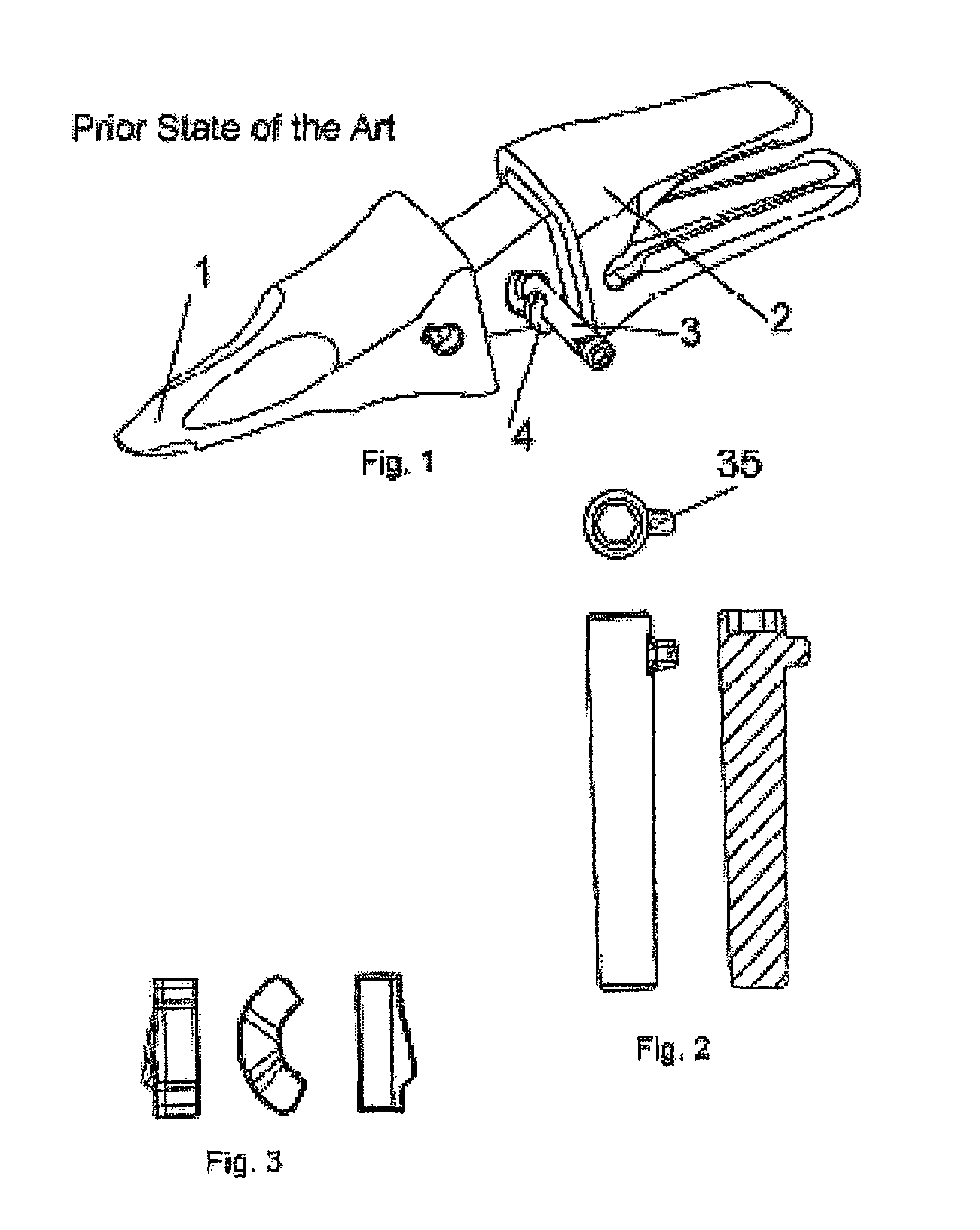
[0050]In reference to FIGS. 1 to 3, which show solutions of the prior state of the art, a tooth-tooth holder assembly is observed comprising a tooth 1 which determines a hollow, a tooth holder 2 with a nose which is housed inside the hollow of the tooth 1, a pin 3, a retainer associated to the pin 5 and an elastic tensor element 35.

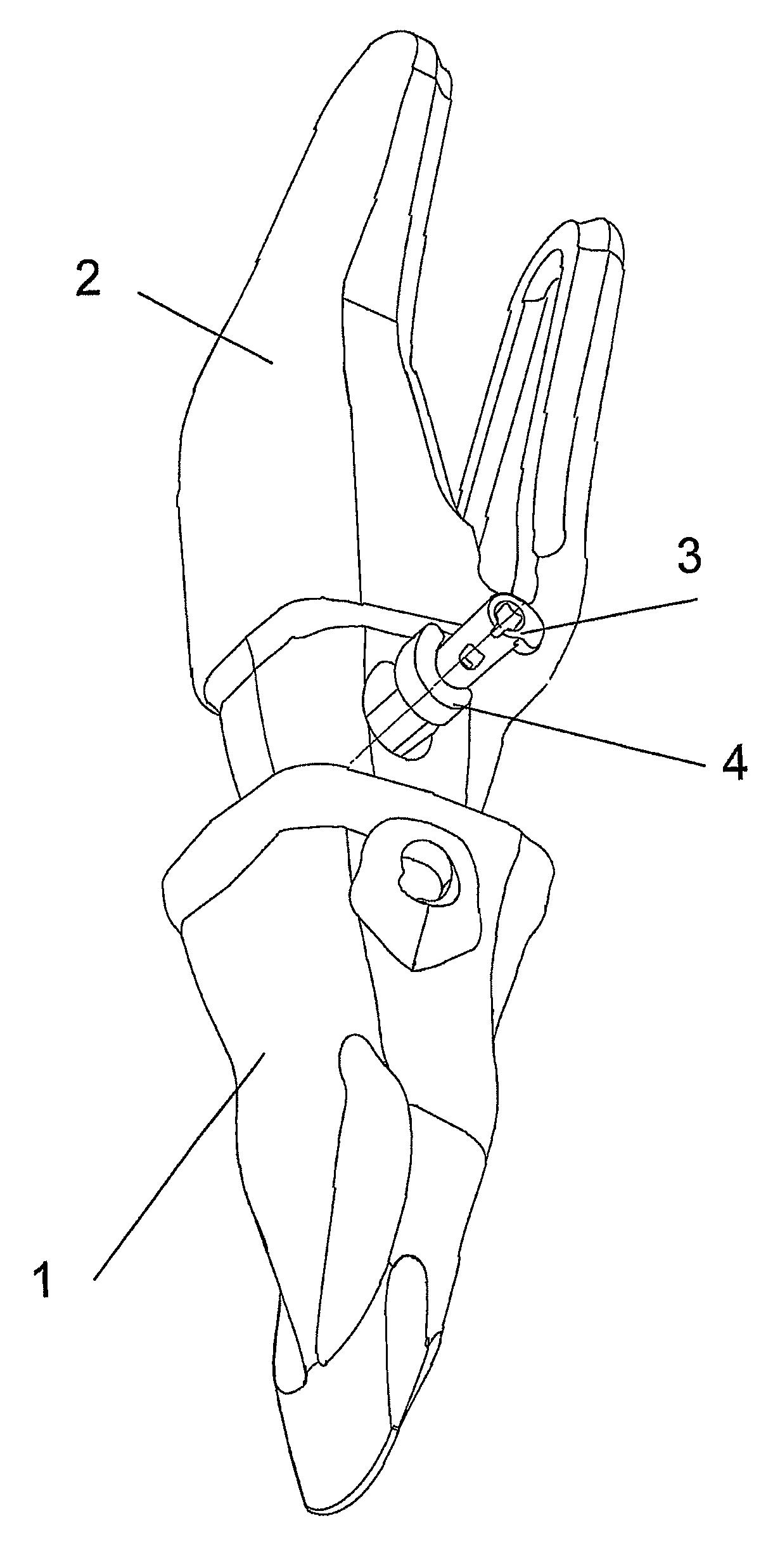
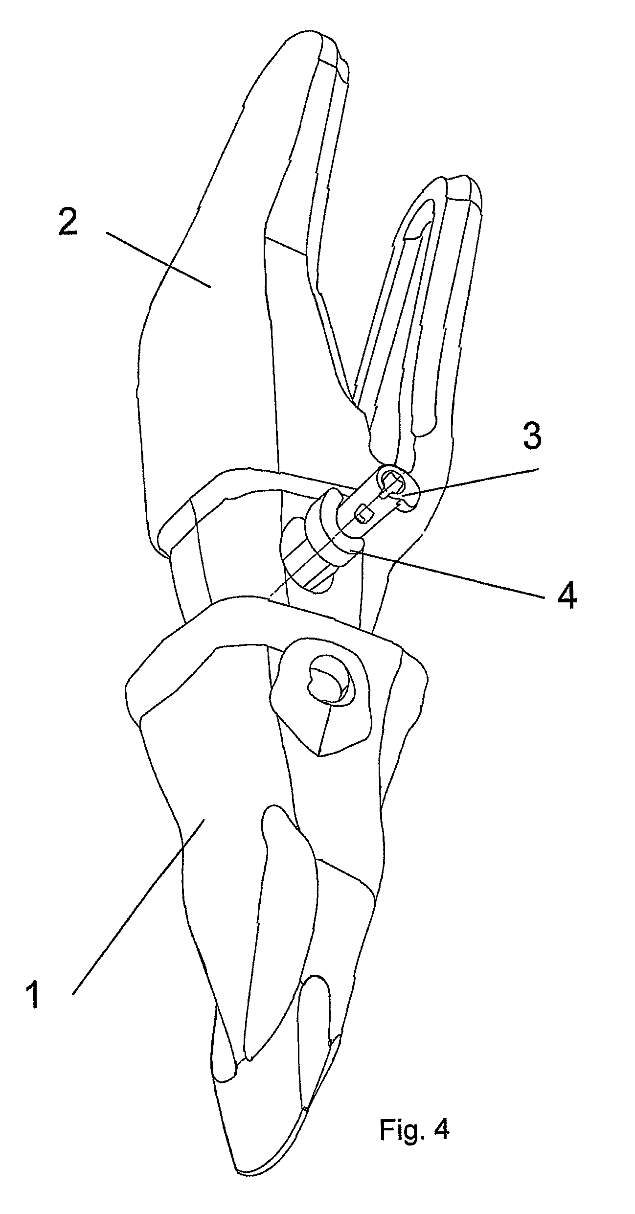
[0051]The following figures refer to a fastening system object of the present invention, between a tooth 1 and a tooth holder 2, in which a pin 3 detachably blocks the tooth 1 with respect to the tooth holder 2, and a retaining element 35 associated to the pin 3 together with an elastically loaded tensor element 4 collaborate to prevent the pin from coming out of its blocking position. A pin is described in the embodiment with a length encompassing the entire ...


PUM


Abstract

Detachable fastening system between a male piece (2) and a female piece (1), pin (3) and female piece (1), specifically for use in machines for moving earth and stones. It is formed by a tooth (2) with a transverse aperture, a tooth holder (2) with another transverse aperture, a pin with an intermediate nipple, and an elastic tensor (4) located in a complementary cavity of the tooth holder (2). The penetration and subsequent rotation of the pin (3) immobilizes it axially, as it is held in said angular position by the action of the tensor (4). In addition, the pin (3) has at one end a projection that interacts with a groove ramped helicoidally and fitted in the aperture of the tooth in order to absorb the axial forces, by unloading the tensor (4) thereof, and also in order to limit the angular distance travelled by the pin between the blocking and unblocking positions, and in order to facilitate possible extraction thereof.

Description

FIELD OF THE INVENTION[0001]The present invention relates to a detachable fastening system between a male piece and a female piece, particularly between a tooth and a tooth holder, and is formed by a tooth, a tooth holder, a pin with an incorporated retaining element which removably blocks said teeth with respect to the tooth holder, and an elastically loaded tensor element, such that the various elements collaborate to prevent the pin from coming out of its blocking position and thus maintain the tooth and tooth holder fastened.[0002]The field of application of the present invention is any in which the mechanical fastening between a male piece and a female piece must be performed, and particularly it can be applied in the sector of moving materials, such as earth and stones, in which the bucket of an excavator is provided with a tooth holder to which teeth are detachably secured, thus allowing the replacement thereof.TECHNICAL BACKGROUND[0003]Machines for moving materials such as e...

Claims


Application Information

Patent Timeline
Patent Type & Authority Patents(United States)
IPC IPC(8): E02F9/28
CPCE02F9/2841E02F9/2833
Inventor LOPEZ ALMENDROS, JOSEPEREZ SORIA, FRANCISCOMARTINEZ, ANGEL
Owner METALOGENIA SA
Why Eureka
Try Eureka