Cover for illuminant and lamp with cover

a technology of cover and lamp, applied in the field of cover for circuit board, can solve the problem of not being easily used for cover, and achieve the effect of improving the lamp assembly

Active Publication Date: 2022-09-06
BJB GMBH & CO KG
View PDF16 Cites 1 Cited by
  • Summary
  • Abstract
  • Description
  • Claims
  • Application Information

AI Technical Summary

Benefits of technology

[0008]Thus, it is an object of the invention to provide a co

Problems solved by technology

The technique proposed in DE 20 2019 106 117 U1 works well in principle but is not easily useable for covers that include additional lamp components on a light exit side, in partic

Method used


Image

  • Cover for illuminant and lamp with cover
  • Cover for illuminant and lamp with cover
  • Cover for illuminant and lamp with cover

Examples


Embodiment Construction

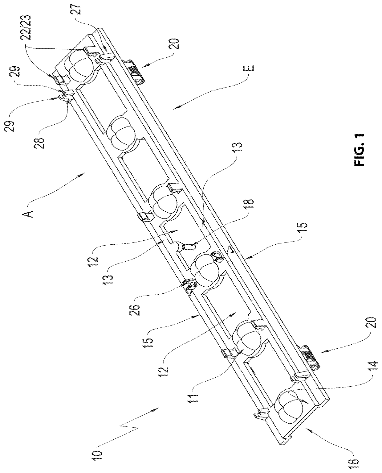
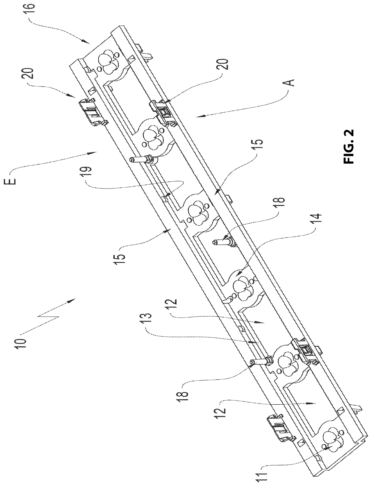
[0027]The drawing figures show a cover according to the invention overall designated with reference numeral 10. The cover 10 is shown in FIGS. 1 and 2 in a perspective view. FIG. 1 shows a perspective view of the light exit side A of the cover 10. FIG. 2 shows a perspective view of the light entry side E of the cover 10. The light exit side A can also be designated as the top side of the cover 10, the light entry side E can be designated as the bottom side of the cover 10.

[0028]The cover 10 includes a plurality of optical elements 11 that are arranged one behind another in a row, wherein cutouts 12 are formed between the optical elements 11. The cutouts 12 are cut outs in the cover 10 which are framed by two adjacent optical elements 11 and two opposite legs 13. The optical elements 11 are formed by a cover wall 14 of the cover 10 that respectively supports a support leg 15 at opposite longitudinal sides. The arrangement plane of the support arms 15 is offset relative to the arrange...


PUM


Abstract

A cover for a circuit board including LED illuminants and at least one connection terminals for connection cables on a top side of the circuit board, the cover including a receiving chamber for the circuit board; a light entry side oriented towards the receiving chamber; a light exit side arranged opposite to the light entry side; fasteners configured to arrange the cover at a light influencing component; optical elements arranged above the LED illuminants and configured to emit light emitted by the LED illuminants, wherein the cover forms a cutout for at least the one connection terminal between two of the optical elements that are adjacent to each other, and wherein the cutout is framed by the cover.

Description

RELATED APPLICATIONS[0001]This application claims priority from and incorporates by reference German Patent Application DE 10 2021 106 644.1 filed on Mar. 18, 2021.FIELD OF THE INVENTION[0002]The invention relates to a cover for a circuit board including LED illuminants and connection terminals for connection cables on a top side of the circuit board.BACKGROUND OF THE INVENTION[0003]Generic covers are known in the art in many shapes and are disclosed e.g; in DE 20 2019 106 117 U1 by applicant.[0004]A use of LEDs as illuminants in lamps typically requires covers in order to adapt radiation properties of the LEDs to a respective application through optical elements. Additionally, the covers are typically used to close the lamp in a light exit direction and in order to make it esthetically appealing.[0005]Increasing efficiency in lamp fabrication is paramount, in particular simplification of lamp assembly, wherein the new design options provided by a utilization of LED illuminants chan...

Claims


Application Information

Patent Timeline
IPC IPC(8): F21V23/00F21S4/28F21V23/06F21V5/00F21Y105/10F21Y115/10
CPCF21V23/005F21S4/28F21V5/007F21V23/009F21V23/06F21Y2105/10F21Y2115/10F21V19/0035F21V19/0045F21V17/164F21Y2103/10F21V13/04F21S8/03F21V7/0083F21V15/013F21V23/002G02B3/0075G02B19/0066G02B19/0028
Inventor HENRICI, PHILIPPBAUMEISTER, OLAFBAECKER, TOBIAS
Owner BJB GMBH & CO KG
Why Eureka
Try Eureka