Electrically contacting an electrical component

a technology for electrical components and electrical contacts, applied in the direction of electrical apparatus, connection, coupling device connections, etc., can solve the problems of copper tabs that copper flows, and copper tabs are difficult to assembl

Inactive Publication Date: 2013-10-15
BOMBARDIER TRANSPORTATION GMBH
View PDF40 Cites 3 Cited by
  • Summary
  • Abstract
  • Description
  • Claims
  • Application Information

AI Technical Summary

Benefits of technology

[0027]Preferably, the first element located farther away from the free end of the pin is made of copper material and the second element located nearer to the free end of the pin is made of steel. As the second element in this case need not be made of particularly good electrically conducting material, steel is sufficient. Steel also has advantages with regard to its hardness. The fastening element can be substantially narrower than the second element so that the contact surface between the fastening element and the second element is relatively small.

Problems solved by technology

However, a disadvantage of this is that the copper flows, i.e., it changes shape, under mechanical pressure over time.
For this reason, the two blades may migrate outward impairing the electrical contact with the contact pin.
There exists the risk of a loss of contact material.
However, such copper tabs are difficult to assemble.

Method used


Image

  • Electrically contacting an electrical component
  • Electrically contacting an electrical component
  • Electrically contacting an electrical component

Examples


Embodiment Construction

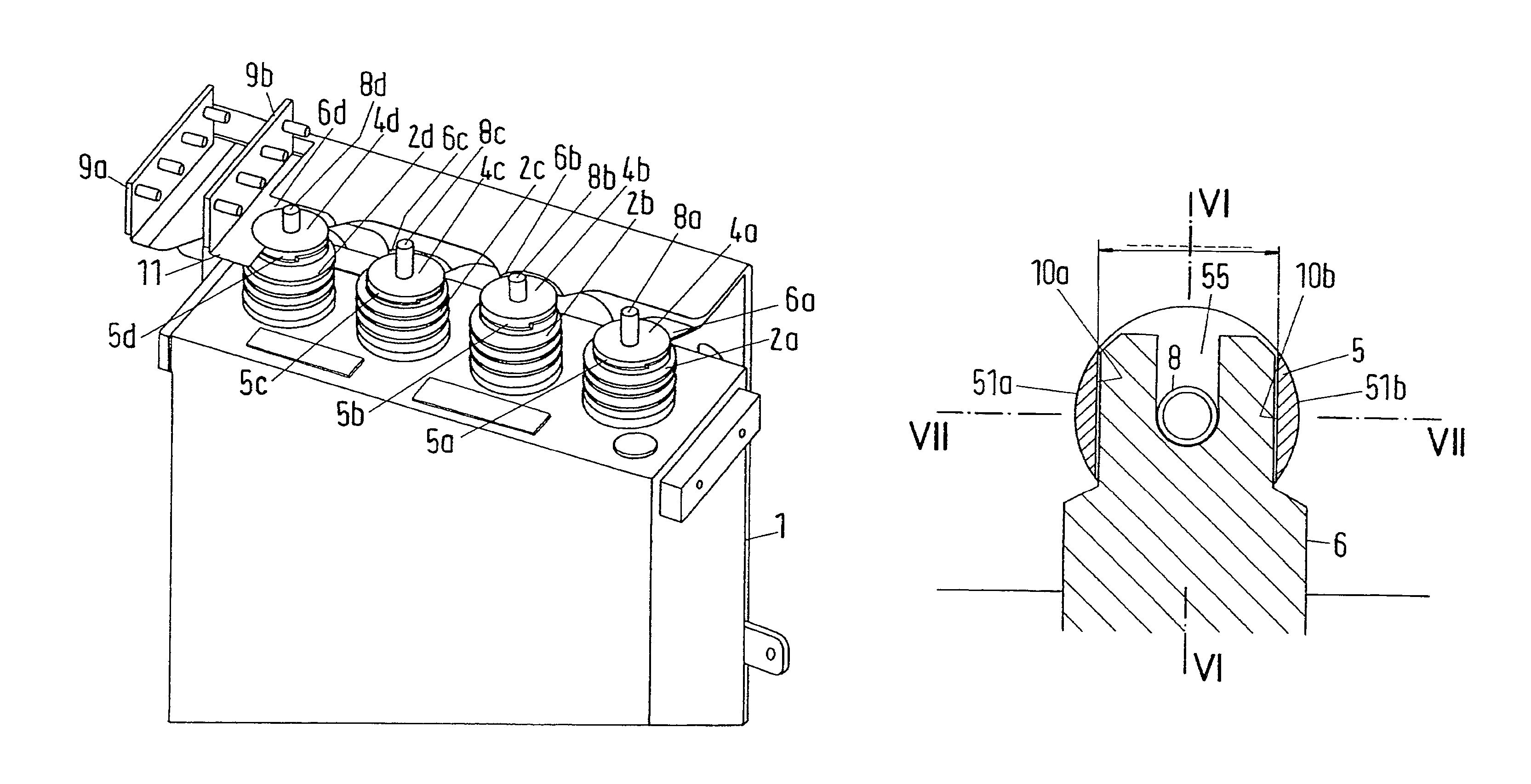
[0046]The block 1 shown in FIG. 1 has four capacitors, the upper end regions of each 2a, 2b, 2c, 2d being depicted. A contact pin 8 protrudes upward from each end region 2. Behind the block 1 can be seen an arrangement of two contact rails for electrically contacting the capacitors. In the area immediately behind the capacitors, the contact rails 9a (the lower contact rail) and 9b (the upper contact rail) are arranged above one another. In this arrangement, the upper contact rail 9b has two contact sheet end regions protruding forward in FIG. 1 in the direction of the upper area 2 of the capacitors. These contact sheet end regions are identified with the reference mark 6b for electrically contacting the upper area 2b using contact pin 8b and with the reference mark 8d for electrically contacting the upper area 2d. In this configuration, the contact sheet end region 6b is slotted and has two blades while the contact sheet end region 6d, while also being slotted, has only one blade an...


PUM


Abstract

Disclosed is an arrangement for electrically contacting a component, in particular a capacitor for a power converter of a rail vehicle, wherein the component includes a protruding pin for applying and / or positioning parts in order to produce the electrical contact. The arrangement a first element which has a through-bore extending in a longitudinal direction therethrough for inserting the pin, a second element which has a through-bore extending in a longitudinal direction therethrough for inserting the pin, and a contact plate of an electrically conductive material, which comprises a contact plate end region. The contact plate end region has a slot extending from a free end into the contact plate end region and the width of the slot is sufficiently large to accommodate the pin.

Description

BACKGROUND OF THE INVENTION[0001]1. Field of the Invention[0002]The invention relates to an arrangement for electrically contacting an electrical component, in particular, a capacitor for a power converter of a rail vehicle. The electrical component has a protruding pin for applying and / or positioning parts of the arrangement in order to produce the electrical contact. The invention further relates to a corresponding method for electrically contacting an electrical component.[0003]2. Description of Related Art[0004]Capacitors have been used for several years to store electrical energy, in particular the braking energy of rail vehicles. The energy stored in the capacitors can be used, in particular, for the next start-up process or acceleration process. Capacitors, however, are also used as filter capacitors in electrical circuits included in power inverters to convert direct current and to operate the traction motors of a rail vehicle. In addition, smoothing capacitors can be used i...

Claims


Application Information

Patent Timeline
Patent Type & Authority Patents(United States)
IPC IPC(8): H01R4/38
CPCH01R4/34H01R2201/26
Inventor SCHUPPLI, RUDOLF
Owner BOMBARDIER TRANSPORTATION GMBH
Why Eureka
Try Eureka