
Temperature-controlled crystal oscillating unit and crystal oscillator

a temperature-controlled crystal and oscillator technology, applied in the field of can solve the problems of inability to accurately detect temperature, damage to conventional temperature-controlled crystal oscillator units, unstable output frequency, etc., and achieve the effect of reducing frequency variation, reducing frequency variation, and simplifying installation and adjustment processes

Inactive Publication Date: 2013-10-15
NIHON DEMPA KOGYO CO LTD
View PDF9 Cites 1 Cited by
  • Summary
  • Abstract
  • Description
  • Claims
  • Application Information

AI Technical Summary

Benefits of technology

The invention provides a temperature-controlled crystal oscillating unit and a crystal oscillator that can stabilize the output frequency, have firmness against shock caused by falling, and are suitable for miniaturization and mass production. The unit includes a crystal plate with electrodes on its surfaces, a heater for heating the crystal plate, and a sensor for detecting the temperature of the crystal plate. The sensor surrounds the electrodes and is connected to terminals on an outer region of the crystal plate through leads. This increases the contact area between the sensor and the crystal plate, resulting in more accurate temperature detection and stabilized output frequency. The structure also has better firmness against vibration and shock. The fabrication process of the unit is simplified because the leads are formed on the connection portion.

Problems solved by technology

However, in the conventional temperature-controlled crystal oscillating unit, the thermocouple is in contact with the crystal blank at one point, and as a result, the temperature cannot be detected accurately and the output frequency thereof is unstable.
In addition, the conventional temperature-controlled crystal oscillating unit is damageable to vibration or shock, and the thermocouple may be separated from the crystal by shock of falling, etc.
Moreover, the conventional temperature-controlled crystal oscillating unit is formed by performing vacuum-sealing into a package respectively, and thus is difficult to be applied in miniaturization and mass production.

Method used


Image

  • Temperature-controlled crystal oscillating unit and crystal oscillator
  • Temperature-controlled crystal oscillating unit and crystal oscillator
  • Temperature-controlled crystal oscillating unit and crystal oscillator

Examples


first embodiment

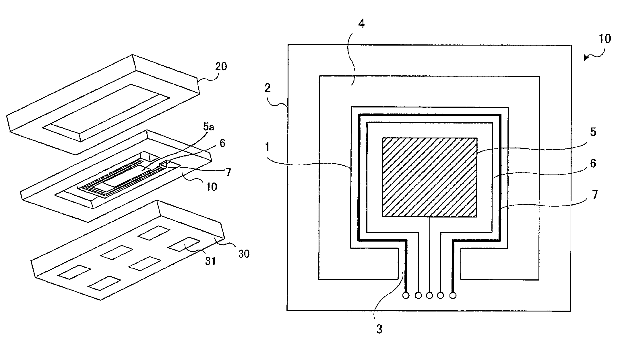
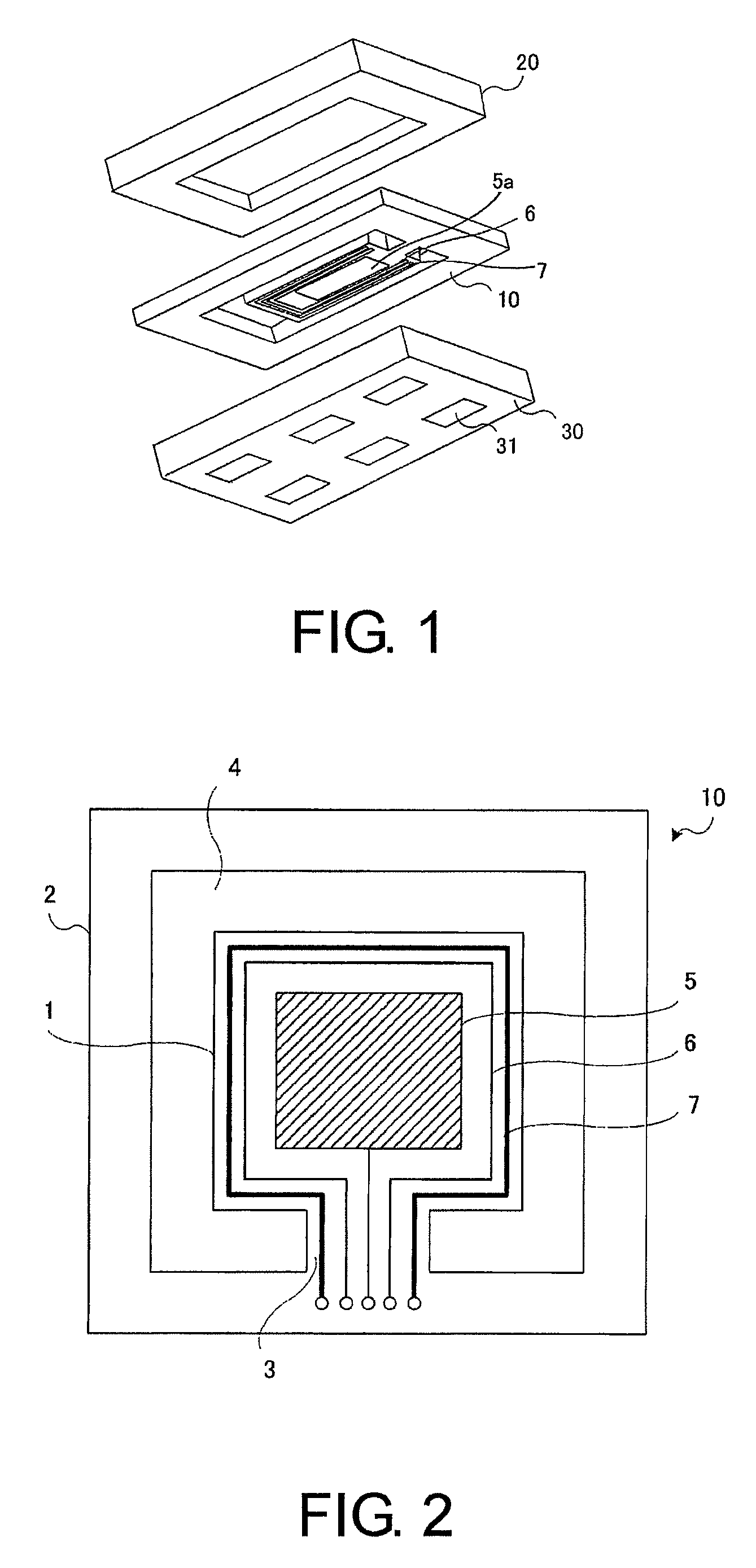
[0050]The structure of a temperature-controlled crystal oscillating unit in the first embodiment of the invention is described in the following paragraphs with reference to FIG. 1. FIG. 1 is a schematic perspective view illustrating the temperature-controlled crystal oscillating unit according to the first exemplary embodiment of the invention. As shown in FIG. 1, the temperature-controlled crystal oscillating unit of the first embodiment (i.e., the first crystal oscillating unit) is formed by clamping, bonding, and vacuum-sealing a crystal blank 10 where an oscillating plate is formed thereon, with a plate 20 and a plate 30 from, top and bottom.

[0051]The crystal blank 10 can be an AT-cut or ST-cut crystal plate, for example. As described below, the crystal blank 10 comprises an outer region, equivalent to an outer frame, and an inner region, equivalent to the oscillating plate. A space (gap) is formed between the outer region and the inner region to separate the outer region from t...

second embodiment

[0063]A crystal blank according to the second embodiment of the invention is described as follows. In the first crystal blank 10, the leads of the crystal electrode 5, the temperature sensor 6 and the heater 7 are arranged parallely on the thin connection portion 3 and a lead pattern is formed on the first crystal blank 10, which is a simple fabrication process. However, because a linewidth of the leads and an interval between the leads need to be narrowed, high-precision delicate processing is required. The crystal blank of the second embodiment of the invention (i.e. second crystal blank) can be fabricated without high-precision delicate processing.

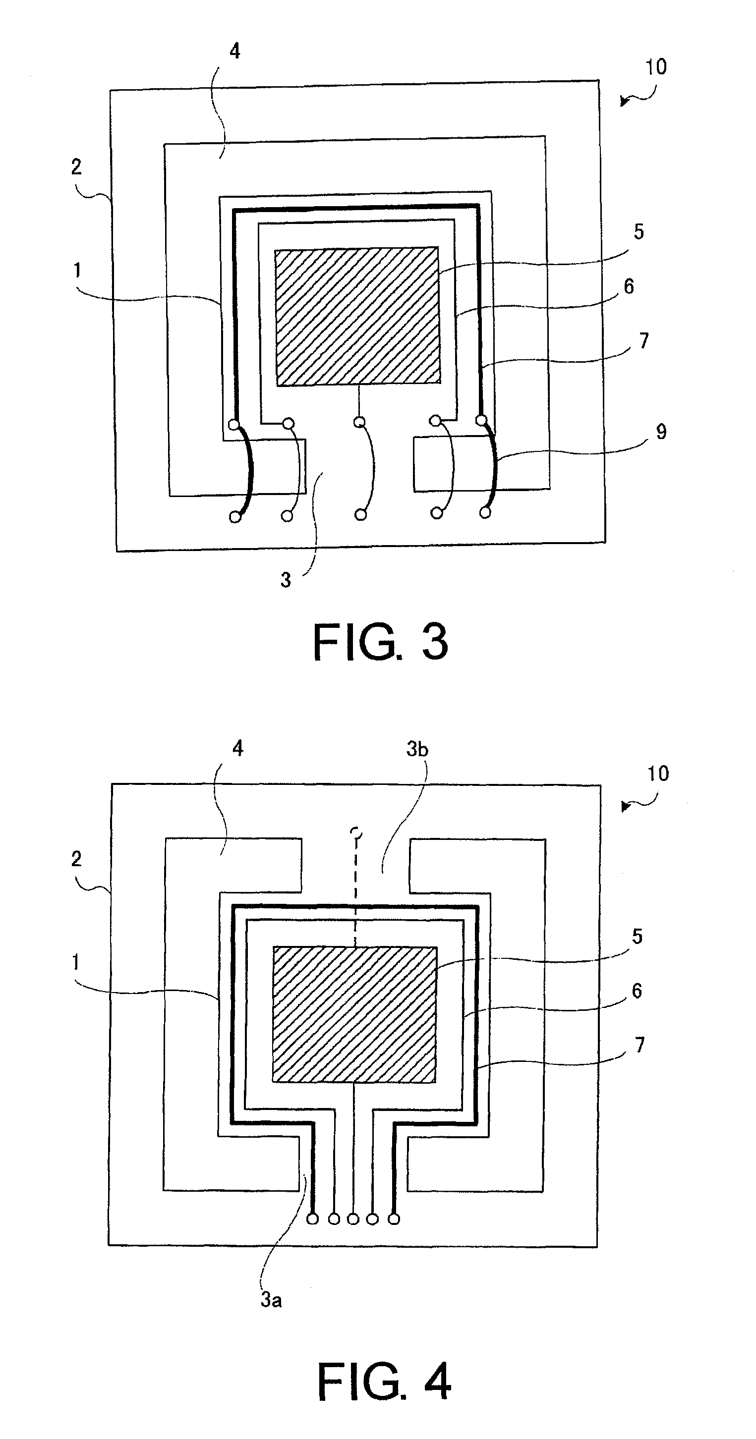
[0064]FIG. 3 is a schematic diagram illustrating a structure of the second crystal blank. As shown in FIG. 3, the second crystal blank comprises an inner region 1 with almost the same structure as that in the first crystal blank. Crystal electrodes 5 are disposed on two opposite surfaces of the inner region 1, and the temperature sensor...

third embodiment

[0068]A crystal blank according to the third embodiment of the invention is described hereinafter with reference to FIG. 5. FIG. 5 is a diagram illustrating the crystal blank according to the third embodiment of the invention. As depicted in FIG. 5, the crystal blank of the third embodiment (i.e. third crystal blank) comprises two connection portions 3a and 3b, and the connection portions 3a and 3b, which connect the inner region 1 with the outer region 2, are disposed on the same side of the inner region 1.

[0069]The structure of the aforesaid inner region 1 is almost the same as that in the first crystal blank. Crystal electrodes 5 are disposed on two opposite surfaces of the inner region 1, and the temperature sensor 6 and the heater 7 are formed to surround three sides of the crystal electrode 5 on one surface of the inner region 1. The leads of the temperature sensor 6 and the heater 7 are formed on the connection portions 3a and 3b to connect the terminals on the outer region 2...


PUM


Abstract

A temperature-controlled crystal oscillating unit and oscillator are provided, which can stabilize an output frequency thereof, have firmness against shock of falling etc., and are suitable for miniaturization and mass production. A crystal blank for the temperature-controlled crystal oscillating unit is formed by an inner region which is an oscillating plate; an outer region which surrounds the periphery of the inner region; and a connection portion which connects the inner region with the outer region. Electrodes are formed on two surfaces of the inner region, and a heater and a temperature sensor are disposed to surround the periphery of the electrode on one surface of the inner region where the electrode is formed thereon. The electrodes, the heater and the temperature sensor are respectively connected with terminals on the outer region by leads. A contact area between the temperature sensor and a crystal is increased.

Description

CROSS-REFERENCE TO RELATED APPLICATION[0001]This application has a priority of Japanese no. 2010-271157 filed Dec. 6, 2010, hereby incorporated by reference.BACKGROUND OF THE INVENTION[0002]1. Field of the Invention[0003]The invention relates to a temperature-controlled crystal oscillating unit and in particular relates to a temperature-controlled crystal oscillating unit and a crystal oscillator, which can stabilize output frequency, have firmness against shock of falling, and are suitable for miniaturization and mass production.[0004]2. Description of the Related Art[0005]The structure of a conventional temperature-controlled crystal oscillating unit is described below with reference to FIG. 8. FIG. 8 is a schematic diagram illustrating the structure of the conventional temperature-controlled crystal oscillating unit (Non-patent Reference 1). Moreover, FIG. 8 is a planar schematic view of the structure depicted in the cross-sectional view of Non-patent Reference 1.[0006]As shown i...

Claims


Application Information

Patent Timeline
Patent Type & Authority Patents(United States)
IPC IPC(8): H03B5/32
CPCH03L1/04
Inventor ASAMURA, FUMIOISHII, TAKEHITO
Owner NIHON DEMPA KOGYO CO LTD
Learn More