Temperature-controlled crystal oscillating unit and crystal oscillator
- Summary
- Abstract
- Description
- Claims
- Application Information
AI Technical Summary
Benefits of technology
Problems solved by technology
Method used
Image
Examples
first embodiment
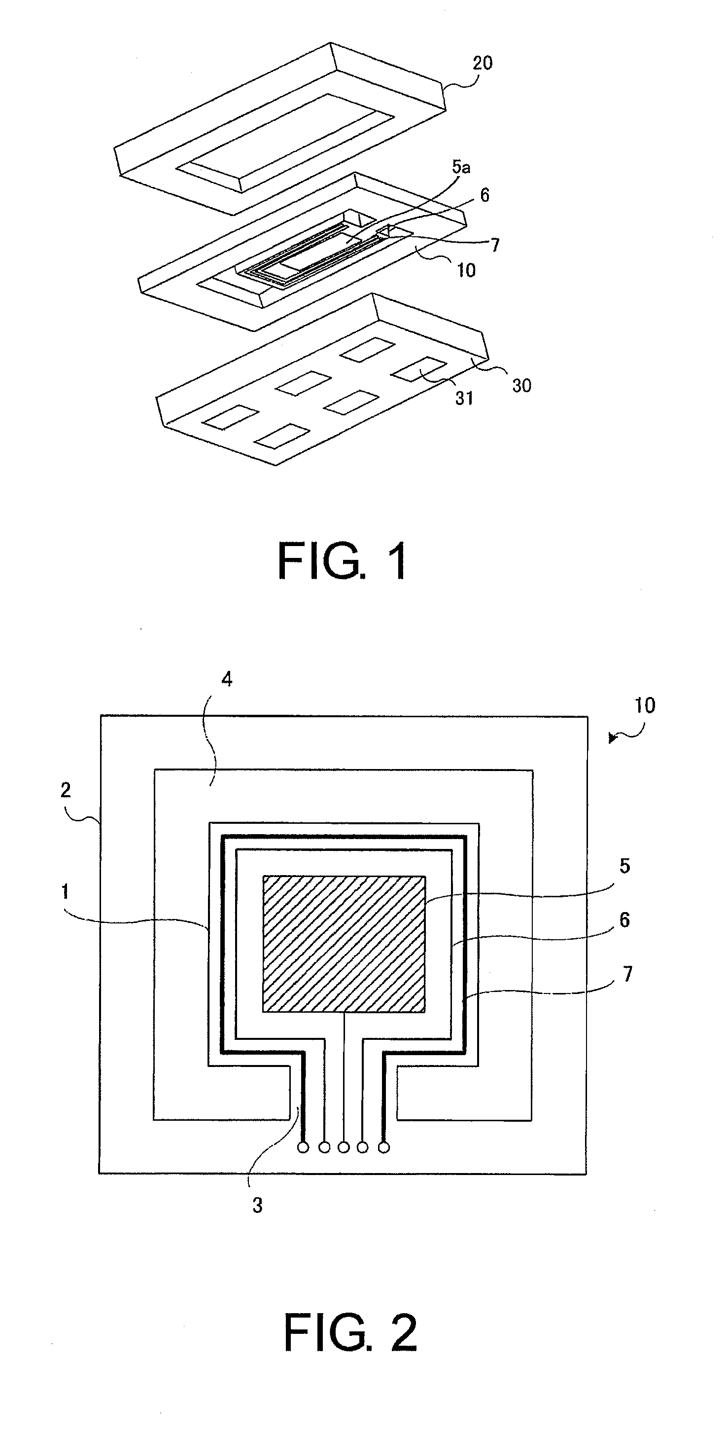
[0050]The structure of a temperature-controlled crystal oscillating unit in the first embodiment of the invention is described in the following paragraphs with reference to FIG. 1. FIG. 1 is a schematic perspective view illustrating the temperature-controlled crystal oscillating unit according to the first exemplary embodiment of the invention. As shown in FIG. 1, the temperature-controlled crystal oscillating unit of the first embodiment (i.e., the first crystal oscillating unit) is formed by clamping, bonding, and vacuum-sealing a crystal blank 10 where an oscillating plate is formed thereon, with a plate 20 and a plate 30 from, top and bottom.
[0051]The crystal blank 10 can be an AT-cut or ST-cut crystal plate, for example. As described below, the crystal blank 10 comprises an outer region, equivalent to an outer frame, and an inner region, equivalent to the oscillating plate. A space (gap) is formed between the outer region and the inner region to separate the outer region from t...
second embodiment
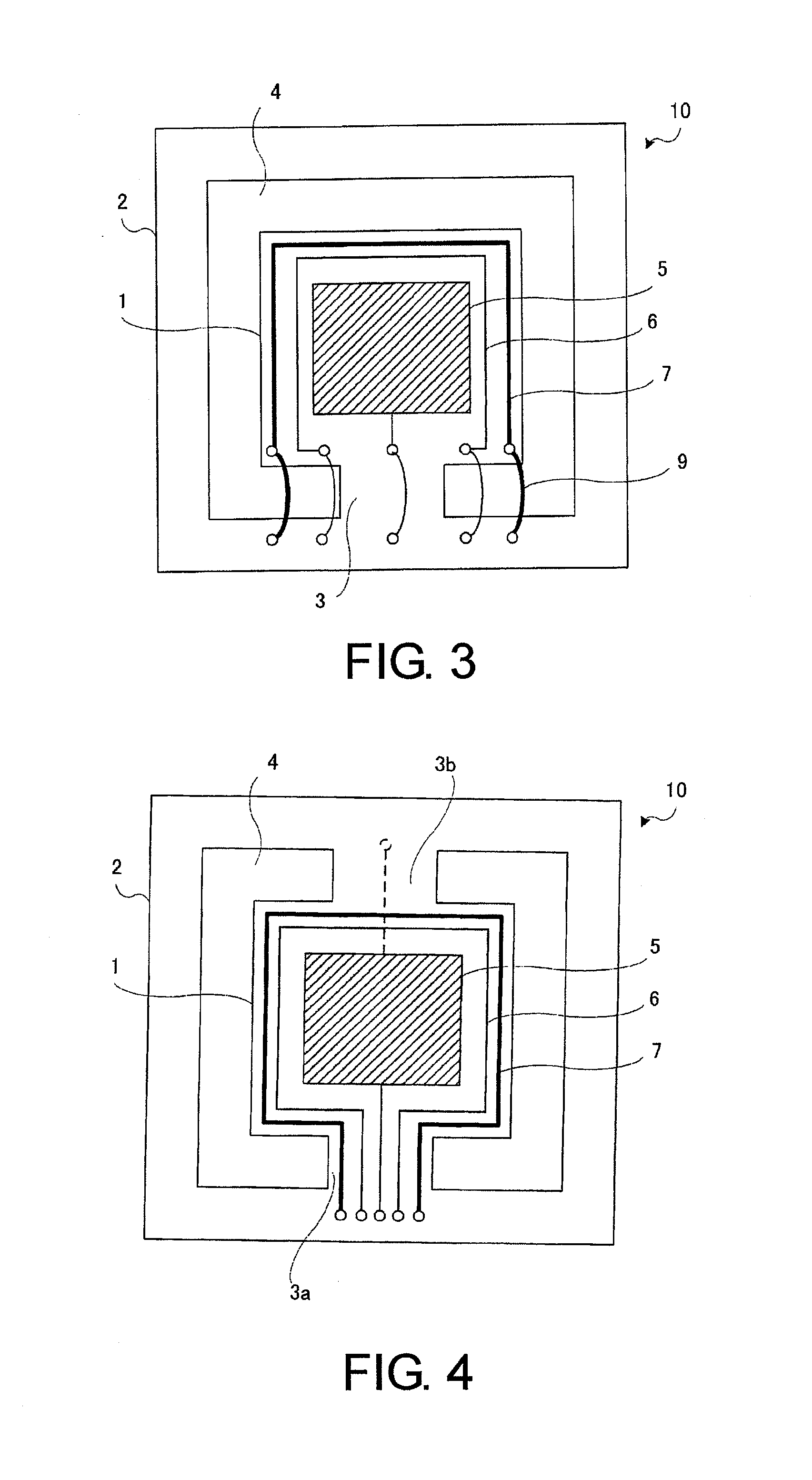
[0063]A crystal blank according to the second embodiment of the invention is described as follows. In the first crystal blank 10, the leads of the crystal electrode 5, the temperature sensor 6 and the heater 7 are arranged parallely on the thin connection portion 3 and a lead pattern is formed on the first crystal blank 10, which is a simple fabrication process. However, because a linewidth of the leads and an interval between the leads need to be narrowed, high-precision delicate proessing is required. The crystal blank of the second embodiment of the invention (i.e. second crystal blank) can be fabricated without high-precision delicate processing.
[0064]FIG. 3 is a schematic diagram illustrating a structure of the second crystal blank. As shown in FIG. 3, the second crystal blank comprises an inner region 1 with almost the same structure as that in the first crystal blank. Crystal electrodes 5 are disposed on two opposite surfaces of the inner region 1, and the temperature sensor ...
third embodiment
[0068]A crystal blank according to the third embodiment of the invention is described hereinafter with reference to FIG. 5. FIG. 5 is a diagram illustrating the crystal blank according to the third embodiment of the invention. As depicted in FIG. 5, the crystal blank of the third embodiment (i.e. third crystal blank) comprises two connection portions 3a and 3b, and the connection portions 3a and 3b, which connect the inner region 1 with the outer region 2, are disposed on the same side of the inner region 1.
[0069]The structure of the aforesaid inner region 1 is almost the same as that in the first crystal blank. Crystal electrodes 5 are disposed on two opposite surfaces of the inner region 1, and the temperature sensor 6 and the heater 7 are formed to surround three sides of the crystal electrode 5 on one surface of the inner region 1. The leads of the temperature sensor 6 and the heater 7 are formed on the connection portions 3a and 3b to connect the terminals on the outer region 2...
PUM
 Abstract
Description
Claims
Application Information
 - R&D
- Intellectual Property
- Life Sciences
- Materials
- Tech Scout
- Unparalleled Data Quality
- Higher Quality Content
- 60% Fewer Hallucinations
Browse by: Latest US Patents, China's latest patents, Technical Efficacy Thesaurus, Application Domain, Technology Topic, Popular Technical Reports.
© 2025 PatSnap. All rights reserved.Legal|Privacy policy|Modern Slavery Act Transparency Statement|Sitemap|About US| Contact US: help@patsnap.com


