
Oscillator

a technology of oscillator and oscillator body, which is applied in the direction of pulse generator, pulse technique, electrical apparatus, etc., can solve the problem that the apparatus cannot solve the above-described problem, and achieve the effect of reducing frequency variation, high accuracy, and simplifying the constitution of the apparatus

Active Publication Date: 2013-11-07
NIHON DEMPA KOGYO CO LTD
View PDF6 Cites 7 Cited by
  • Summary
  • Abstract
  • Description
  • Claims
  • Application Information

AI Technical Summary

Benefits of technology

The present invention relates to an oscillator that can adjust its output to compensate for changes in temperature. The oscillator has two circuits that produce an oscillation output. The difference between these outputs is measured and used to control a signal processing unit that generates a control signal to adjust the output of the oscillator. This helps achieve a more stable output even at different temperatures. The oscillator can switch between different modes to connect to the external computer or signal processing unit. A storage unit stores a parameter used in the signal processing unit, which simplifies the circuit design and reduces the need for a dedicated terminal. The technical effect of this invention is to provide a stable output from the oscillator regardless of changes in temperature, which can improve the accuracy and reliability of the signal processing system.

Problems solved by technology

However, this apparatus cannot solve the above-described problem.

Method used


Image

  • Oscillator
  • Oscillator
  • Oscillator

Examples


Embodiment Construction

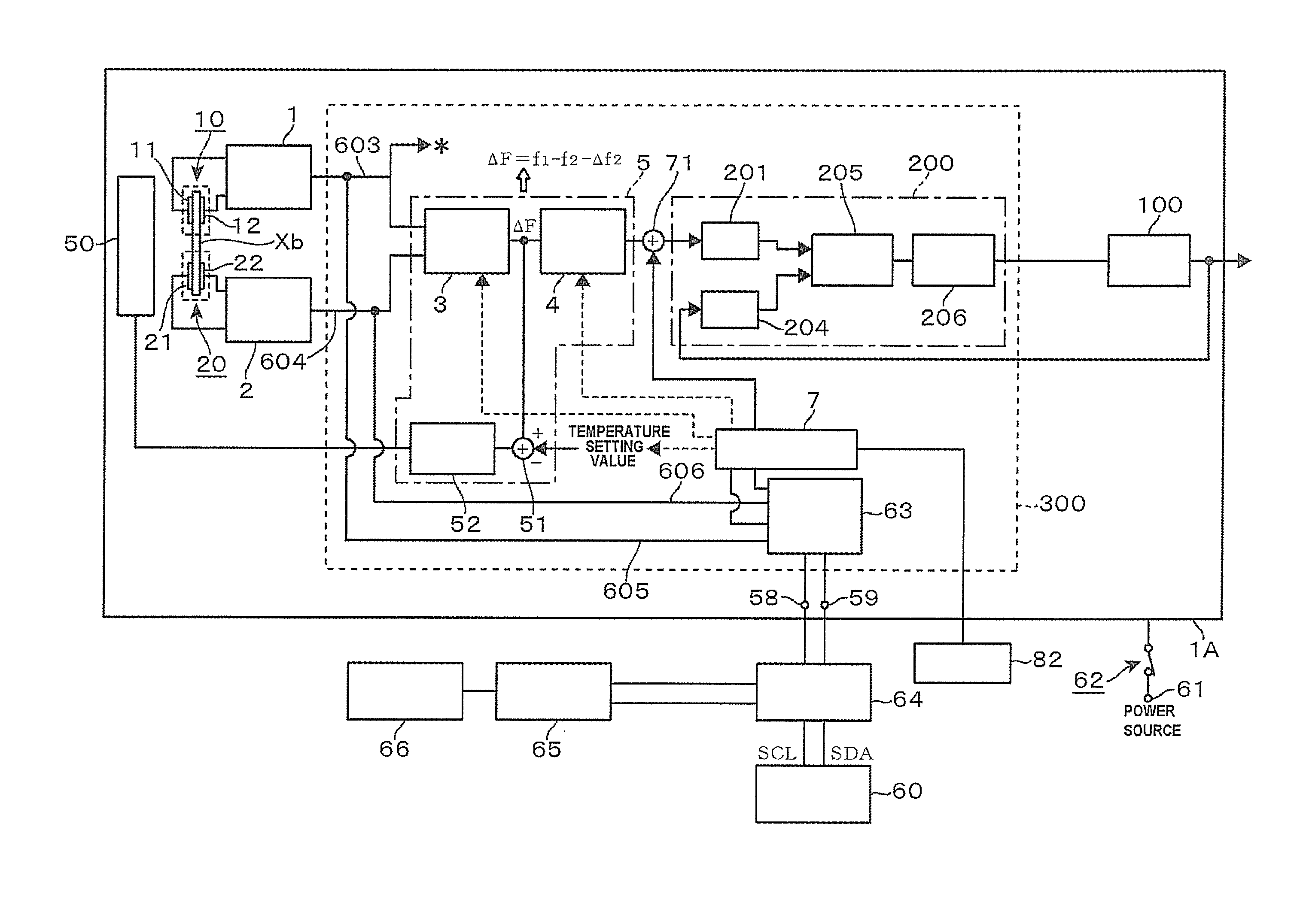
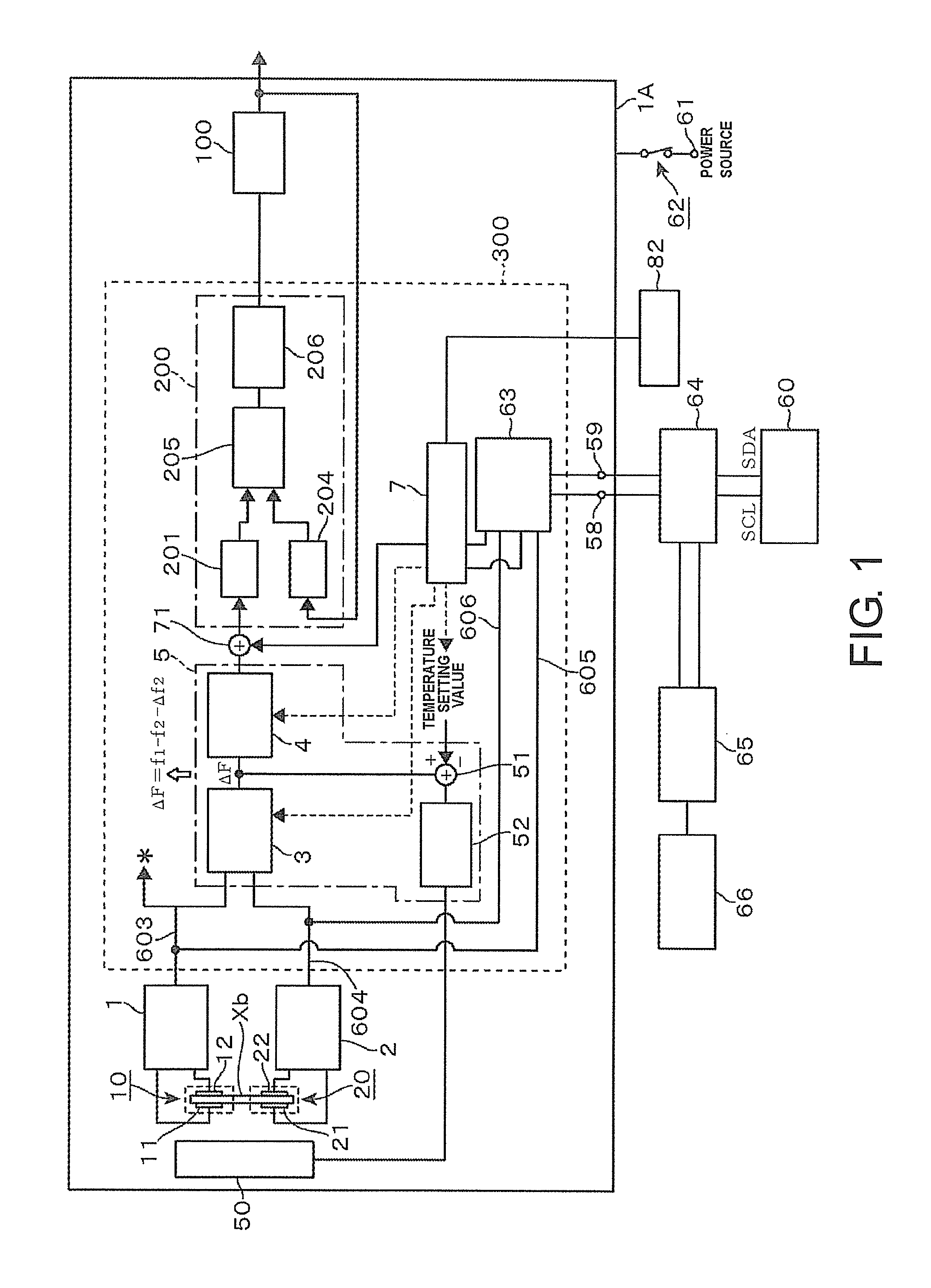
[0029]FIG. 1 is a block diagram illustrating an entire oscillator 1A constituted by applying a crystal controlled oscillator according to an embodiment of the present disclosure. This oscillator 1A is constituted as a frequency synthesizer that outputs a frequency signal at a set frequency. The oscillator 1A includes a voltage control oscillator 100 employing a crystal unit, a control circuit unit 200, which constitutes PLL for the voltage control oscillator 100, a crystal controlled oscillator (a reference numeral is not given), and a heater circuit 50. The crystal controlled oscillator generates a clock signal to operate a DDS circuit unit 201 that generates a reference signal of the PLL. The heater circuit 50 adjusts temperature of atmosphere around crystal units 10 and 20 in this crystal controlled oscillator. Hence, the crystal controlled oscillator is Oven-Controlled Crystal Oscillators (OCXO).

[0030]The control circuit unit 200 is PLL (Phase locked loop). The control circuit u...


PUM


Abstract

An oscillator outputs a control signal to suppress an influence caused by temperature characteristic of f1 based on a differential signal corresponding to difference between an oscillation output f1 of a first oscillator circuit and an oscillation output f2 of a second oscillator circuit treated as a temperature detection value. A switching unit switches between a first state and a second state. The first state is a state where a first connecting end and a second connecting end are connected to a storage unit for access from an external computer to the storage unit. The second state is a state where the first connecting end and the second connecting end are connected to a first signal path and a second signal path such that the respective f1 and f2 are retrieved from the first connecting end and the second connecting end to an external frequency measuring unit.

Description

CROSS REFERENCE TO RELATED APPLICATIONS[0001]This application claims the priority benefit of Japan application serial no. 2012-104726, filed on May 1, 2012. The entirety of the above-mentioned patent application is hereby incorporated by reference herein and made a part of this specification.TECHNICAL FIELD[0002]This present disclosure relates to an oscillator where a signal corresponding to a difference between an oscillation output f1 of a first oscillator circuit and an oscillation output f2 of a second oscillator circuit is treated as a temperature detection value and reduces an influence caused by temperature characteristic of f1.DESCRIPTION OF THE RELATED ART[0003]FIG. 18 illustrates a general constitution of Temperature Compensated Crystal Oscillator (TCXO), which is an oscillator. Reference numeral 90 denotes a crystal unit, and reference numeral 91 denotes an oscillator circuit. Changing a control voltage supplied from a control voltage generator 93 to a voltage variable ca...

Claims


Application Information

Patent Timeline
Patent Type & Authority Applications(United States)
IPC IPC(8): H03L1/02
CPCH03L1/02H03K3/011H03L1/022
Inventor YORITA, TOMOYA
Owner NIHON DEMPA KOGYO CO LTD
Learn More