Jaw structure for electrosurgical instrument and method of use

a jaw structure and electrosurgical technology, applied in the field of medical devices and techniques, can solve the problems of ineffective bipolar instruments in sealing or welding many types of tissues, non-uniform sealing of tissue, and rf jaws that engage opposing sides of tissue volume, so as to reduce rf energy application, prevent any substantial dehydration of tissue, and increase resistance

Inactive Publication Date: 2006-03-14
ETHICON ENDO SURGERY INC
View PDF159 Cites 2022 Cited by
  • Summary
  • Abstract
  • Description
  • Claims
  • Application Information

AI Technical Summary

Benefits of technology

[0010]In one exemplary embodiment, a jaw of the instrument defines a tissue engagement plane that engages the tissue targeted for welding. The engagement plane carries first and second surface portions that comprise, respectively: (i) an electrically conductive material and (ii) a positive temperature coefficient (PTC) material having a selected increased resistance that differs at selected increased temperatures thereof. One type of PTC material is a ceramic that can be engineered to exhibit a selected positively slope curve of temperature-resistance over a temperature range of about 37° C. to 100° C. The region at the higher end of such a temperature range brackets a targeted “thermal treatment range” at which tissue can be effectively welded. The selected resistance of the PTC matrix at the upper end of the temperature range will substantially terminate current flow therethrough.
[0011]In operation, it can be understood that the engagement plane will apply active Rf energy (ohmic heating within) to the engaged tissue until the point in time that the PTC matrix is heated to exceed the maximum of the thermal treatment range. Thereafter, Rf current flow from the engagement surface will be lessened—depending on the relative surface areas of the first and second surface portions. This instant and automatic reduction of Rf energy application can be relied on to prevent any substantial dehydration of tissue proximate to the engagement plane. By thus maintaining an optimal level of moisture around the engagement plane, the working end can more effectively apply energy to the tissue—and provide a weld thicker tissues with limited collateral thermal effects.
[0012]The jaw assembly corresponding to the invention further provides a suitable cross-section and mass for providing a substantial heat capacity. Thus, when the PTC matrix is elevated in temperature to the selected thermal treatment range, the retained heat of the matrix volume can effectively conduct thermal energy to the engaged tissue volume. Thus, in operation, the working end can automatically modulate the application of energy to tissue between active Rf heating and passive conductive heating of the targeted tissue to maintain the targeted temperature level.

Problems solved by technology

While such bi-polar jaws can adequately seal or weld tissue volumes that have a small cross-section, such bi-polar instruments often are ineffective in sealing or welding many types of tissues, such as anatomic structures having walls with irregular or thick fibrous content, bundles of disparate anatomic structures, substantially thick anatomic structures, or tissues with thick fascia layers such as large diameter blood vessels.
Prior art Rf jaws that engage opposing sides of a tissue volume typically cannot cause uniform thermal effects in the tissue, whether the captured tissue is thin or substantially thick.
Localized tissue desiccation and charring can occur almost instantly as tissue impedance rises, which then can result in a non-uniform seal in the tissue.
The typical prior art Rf jaws can cause further undesirable effects by propagating Rf density laterally from the engaged tissue to cause unwanted collateral thermal damage.

Method used


Image

  • Jaw structure for electrosurgical instrument and method of use
  • Jaw structure for electrosurgical instrument and method of use
  • Jaw structure for electrosurgical instrument and method of use

Examples


Embodiment Construction

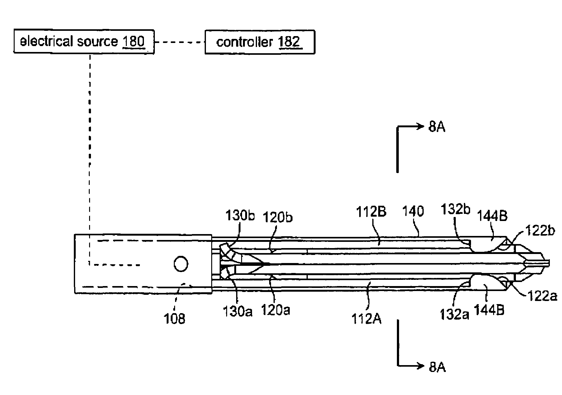
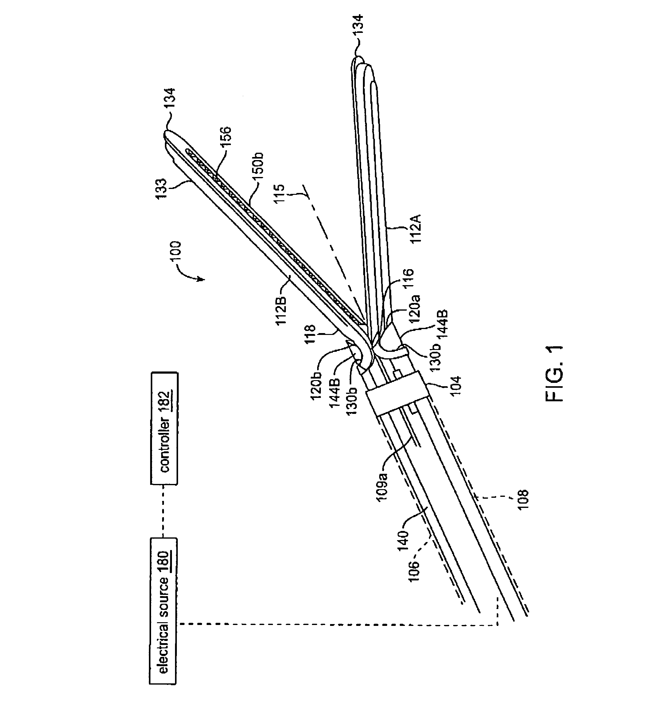
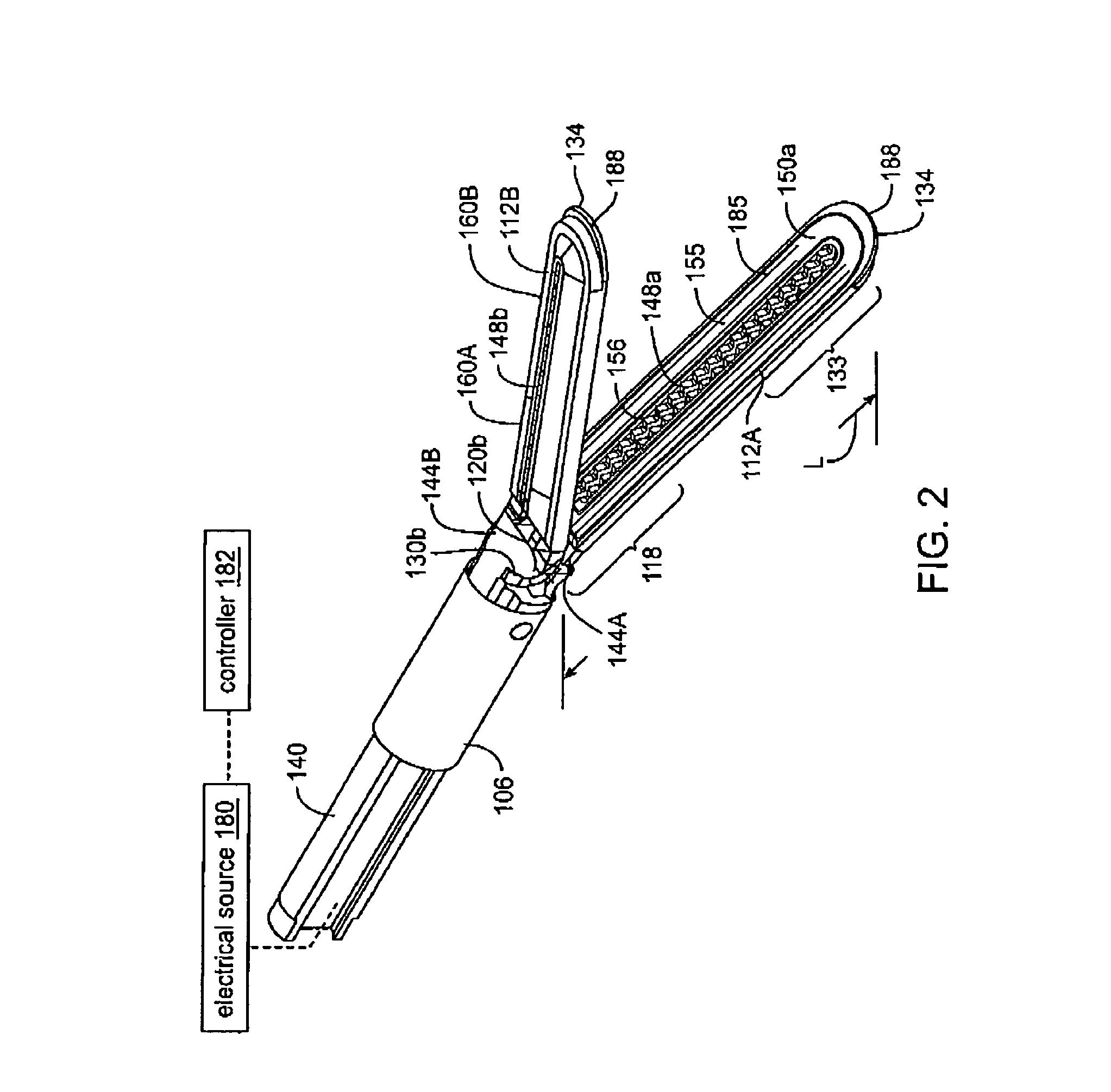
[0032]1. Type “A” jaw assembly. An exemplary Type “A” working end and jaw assembly 100 of a surgical grasping instrument is illustrated in FIGS. 1 and 2, which is adapted for transecting captured tissue and contemporaneous welding of the captured tissue with Rf energy delivery. The jaw assembly 100 is carried at the distal end 104 of an introducer sleeve member 106 that can be rigid, articulatable or deflectable in any suitable diameter. For example, the introducer sleeve portion 106 can have a diameter ranging from about 2 mm. to 20 mm. to cooperate with cannulae in endoscopic surgeries or for use in open surgical procedures. The introducer portion 106 extends from a proximal handle (not shown). The handle can be any type of pistol-grip or other type of handle known in the art that carries actuator levers, triggers or sliders for actuating the jaws as will be disclosed below, and need not be described in further detail. The introducer sleeve portion 106 has a bore 108 extending the...


PUM

PropertyMeasurementUnit
temperatureaaaaaaaaaa
diameteraaaaaaaaaa
lengthaaaaaaaaaa

Abstract

An electrosurgical medical device and technique for creating thermal welds in engaged tissue that provides very high compressive forces. In one exemplary embodiment, at least one jaw of the instrument defines a tissue engagement plane carrying first and second surface portions that comprise (i) an electrically conductive material and (ii) a positive temperature coefficient (PTC) material having a selected increased resistance that differs at each selected increased temperature over a targeted treatment range. One type of PTC material is a doped ceramic that can be engineered to exhibit a selected positively sloped temperature-resistance curve over about 37° C. to 100° C. The 70° C. to 100° C. range can bracket a targeted “thermal treatment range” at which tissue welded can be accomplished. The engineered resistance of the PTC matrix at the upper end of the temperature range will terminate current flow through the matrix. In one mode of operation, the engagement plane cause ohmic heating within tissue from Rf energy delivery tissue PTC matrix is heated to exceed the treatment range. Thereafter, energy density in the engaged tissue will be modulated as the conductivity of the second portion hovers within the targeted treatment range to thereby provide optical tissue heating for purposes of tissue welding.

Description

CROSS-REFERENCE TO RELATED APPLICATION[0001]This application claims benefit from Provisional U.S. Patent Application Ser. No. 60 / 347,382 filed Jan. 11, 2002 having the same title as above, and this application is a Continuation-in-part of U.S. patent application Ser. No. 10 / 032,867 filed Oct. 22, 2001, now issued as U.S. Pat. No. 6,929,644 and titled Electrosurgical Jaw Structure for Controlled Energy Delivery, both of which applications are incorporated herein by this reference.BACKGROUND OF THE INVENTION[0002]1. Field of the Invention[0003]This invention relates to medical devices and techniques and more particularly relates to a simplified electrosurgical jaw structure (i) that provides positive cam engagements for both opening the jaws and closing the jaws, and (ii) that provides self-modulating Rf energy application to tissue from a conductive-resistive matrix in at least one jaw's engagement surface.[0004]2. Description of the Related Art[0005]In various open and laparoscopic ...

Claims


Application Information

Patent Timeline
Patent Type & Authority Patents(United States)
IPC IPC(8): A61B18/12A61B18/14
CPCA61B18/1442A61B2018/00077A61B2018/0063A61B2018/00148A61B2018/00083A61B18/1445A61B2018/1455
Inventor TRUCKAI, CSABABAKER, JAMES A.SHADDUCK, JOHN H.
Owner ETHICON ENDO SURGERY INC
Why Eureka
Try Eureka