Rotating thumb safety fuze for a hand grenade and related methods of operation and assembly

Inactive Publication Date: 2013-10-22
UNITED STATES OF AMERICA THE AS REPRESENTED BY THE SEC OF THE ARMY
View PDF22 Cites 16 Cited by
  • Summary
  • Abstract
  • Description
  • Claims
  • Application Information

AI Technical Summary

Benefits of technology

[0018]The present safety fuze provides numerous advantages among which are the following:
[0020]The safety fuze also provides a means to test the squeeze pressure of the lever and break away force of the thumb switch 100% during manufacturing. This eliminates the sampling of production parts off the line and nearly eliminates the probability of an escape of a fuze that does not meet the specified forces.
[0024]The safety fuze provides assurance that the user has control of the lever before arming. The thumb switch will not rotate until the lever is squeezed, which mandates a firm grip on the safety fuze.
[0026]The safety fuze reduces the potential for field modification by the user and reduces the subjectivity of the disposition of condition code during turn in.
[0027]The safety fuze reduces and simplifies the steps required to deploy the grenade compared to current designs, resulting in faster deployment during training and combat environments.

Problems solved by technology

However, these conventional designs could present various inherent problems, particularly when used in the field, under adverse and stressful conditions.
More specifically, many conventional hand grenade fuze designs include an explosive train that is always in-line from production through employment, thus presenting an intrinsic danger of inadvertent initiation.
In addition, other fuzes are designed primarily for right handed users and require different grasp and inverted handling for left-handed users, thus increasing the possibility of slippage, “milking” and functioning within close proximity.
Conventional fuze designs do not provide a visual indication (e.g., color coded) of the fuze armed and unarmed states, thus increasing the risk of inadvertently confusing the armed state for the unarmed state and creating subjective disposition of unexploded and mishandled grenades.
Certain conventional fuze designs provide for two safety features that are not required to be performed in a specific order, thus increasing the risk of unintentional functioning.
Conventional fuze designs cannot be easily returned to a safe state by the user once the safety pin is removed.
Conventional fuze designs do not necessarily provide a fail safe feature on the primary safety.
The primary safety of some of these designs can be easily modified or altered by the user, or damaged by impact.
Consequently, reducing the effectiveness of the primary safety and creating a risk of unintentional initiation.
The fuze primary safety design is generally tested through destructive testing, and the results are based on the sample size and the statistical analysis of results, thus the results have a high confidence level but are never 100% for the lot.
Conventional fuze designs intend for the user to have a secure grip on the lever when removing the primary safety pin but have no mechanical means to ensure this condition exists.
The spatial constraints on existing fuze designs pose technical risk for incorporating electronic circuitry to accomplish the detonation delay with an out-of-line explosive train.

Method used


Image

  • Rotating thumb safety fuze for a hand grenade and related methods of operation and assembly
  • Rotating thumb safety fuze for a hand grenade and related methods of operation and assembly
  • Rotating thumb safety fuze for a hand grenade and related methods of operation and assembly

Examples


Embodiment Construction

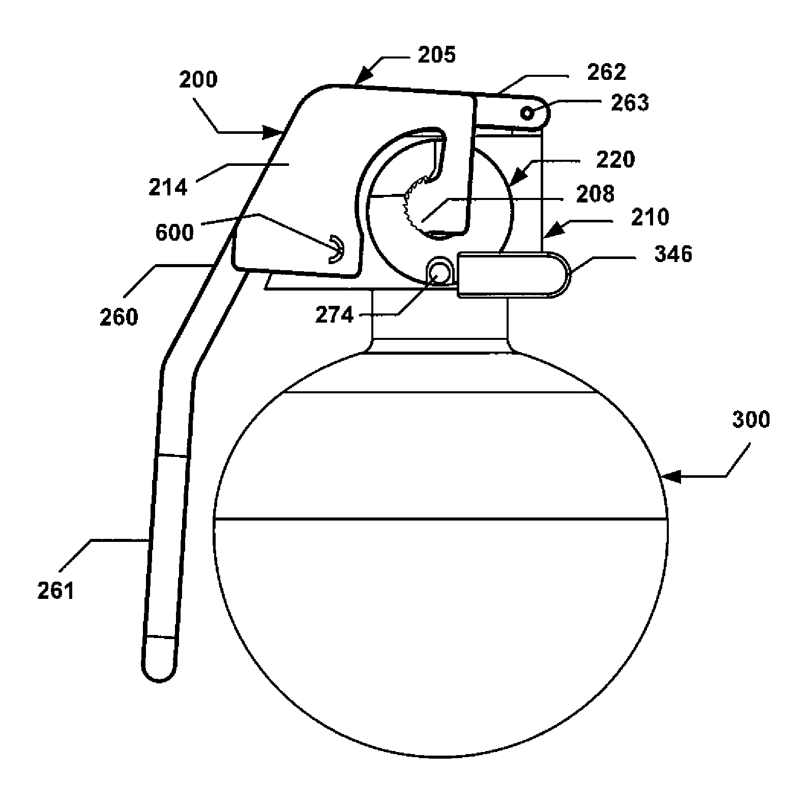
[0046]A safety fuze 200 of the present invention and its method of operation will now be described with reference to FIGS. 1 and 2. The safety fuze 200 generally includes a lever 205, a body 210, a striker assembly 279, and a rotating thumb switch assembly 350.

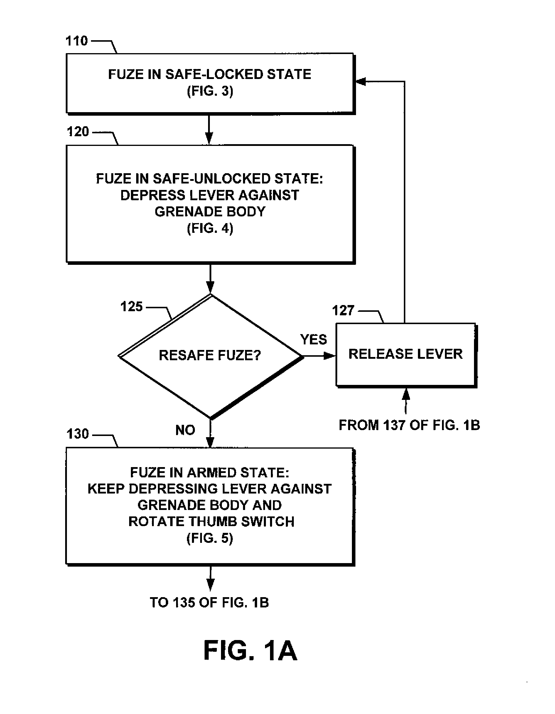
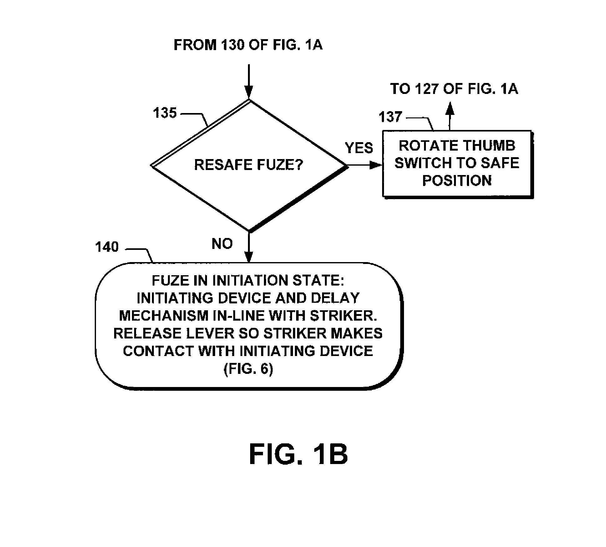
[0047]The general operation 100 of the safety fuze 200 involves four distinct stages. In the first operation stage, the safety fuze 200 is in a safe-locked state, as shown in step 110 of FIG. 1A. As used herein, the terms “state,”“position,” or “stage” are used interchangeably. In this state, the lever 205 is locked in place by the rotating thumb switch assembly 350. In turn, the lever 205 holds back the striker assembly 279 under spring tension.

[0048]The lever 205 is held at a distance from the body 210 and prevented from rotation (e.g., FIG. 3A). In this safe-locked state, the rotating switch assembly 350 contains an initiation and / or delay device 355 (shown in dashed line in FIG. 3D), and is rotated 90 degrees away from a p...


PUM


Abstract

A safety fuze for use with a canister, includes a body, a lever that is rotatably secured to one end of the body, a striker assembly that is rotatably secured to another end of the body, and a thumb switch assembly that includes a target and that is rotatably secured to the body. The safety fuze is selectively armed and disarmed. It is settable in one or four states: a safe-locked state; a safe-unlocked state; an armed state; and an initiation state.

Description

GOVERNMENTAL INTEREST[0001]The invention described herein may be manufactured and used by, or for the Government of the United States for governmental purposes without the payment of any royalties thereon.FIELD OF THE INVENTION[0002]The present invention relates in general to the field of munitions. More specifically, this invention relates to safety fuzes for hand emplaced grenades for military and commercial uses.BACKGROUND OF THE INVENTION[0003]Safety is a very important design aspect of a hand grenade fuze. Conventional fuze designs account for a time delay period from initiation, for the detonation to occur, in order to ensure that the grenade is cast outside the explosion hazard area.[0004]To this end, numerous conventional hand grenade fuzes have been proposed, some of which are described in the following publications: U.S. Pat. Nos. 3,823,669; 3,926,122; 4,063,514; 4,167,905; 4,730,559; 5,196,649; 6,082,267; 6,965,542; 7,197,983; and 7,712,419, and Statutory Invention Regist...

Claims


Application Information

Patent Timeline
IPC IPC(8): F42B27/00F42C15/188F42C15/20
CPCF42C15/188F42C15/20F42B27/08
Inventor LAUCH, RICHARD
Owner UNITED STATES OF AMERICA THE AS REPRESENTED BY THE SEC OF THE ARMY
Why Eureka
Try Eureka