Deck ledge table

a technology of ledges and tables, applied in the field of support surfaces, can solve the problems of limited surface area, limited space on the surface, and the need to disassemble the engagement mechanism of the table on the non-horizontal support surface,

Inactive Publication Date: 2013-10-22
RAML JOSEPH P
View PDF28 Cites 22 Cited by
  • Summary
  • Abstract
  • Description
  • Claims
  • Application Information

AI Technical Summary

Benefits of technology

[0009]According to another aspect of the present disclosure, a biasing member is positioned around the screw between the back clamp and the table section. The biasing member provides a force against the movement of the back clamp towards the table section that aids in disengagement of the back clamp and table section from the vertical structure(s), easing the removal of the table.

Problems solved by technology

However, in certain environments there is a limited amount of space on a surface upon which to support a table.
However, one main drawback for these types of tables adapted for use with a non-horizontal support surface is that the engagement mechanism holding the table on the non-horizontal support surface must be disassembled and / or removed from the table in order relocate the table from one location to another.
Also, in many situations there is a limited amount of surface area available on which tables, chairs and other items can be positioned.

Method used


Image

  • Deck ledge table
  • Deck ledge table
  • Deck ledge table

Examples


Embodiment Construction

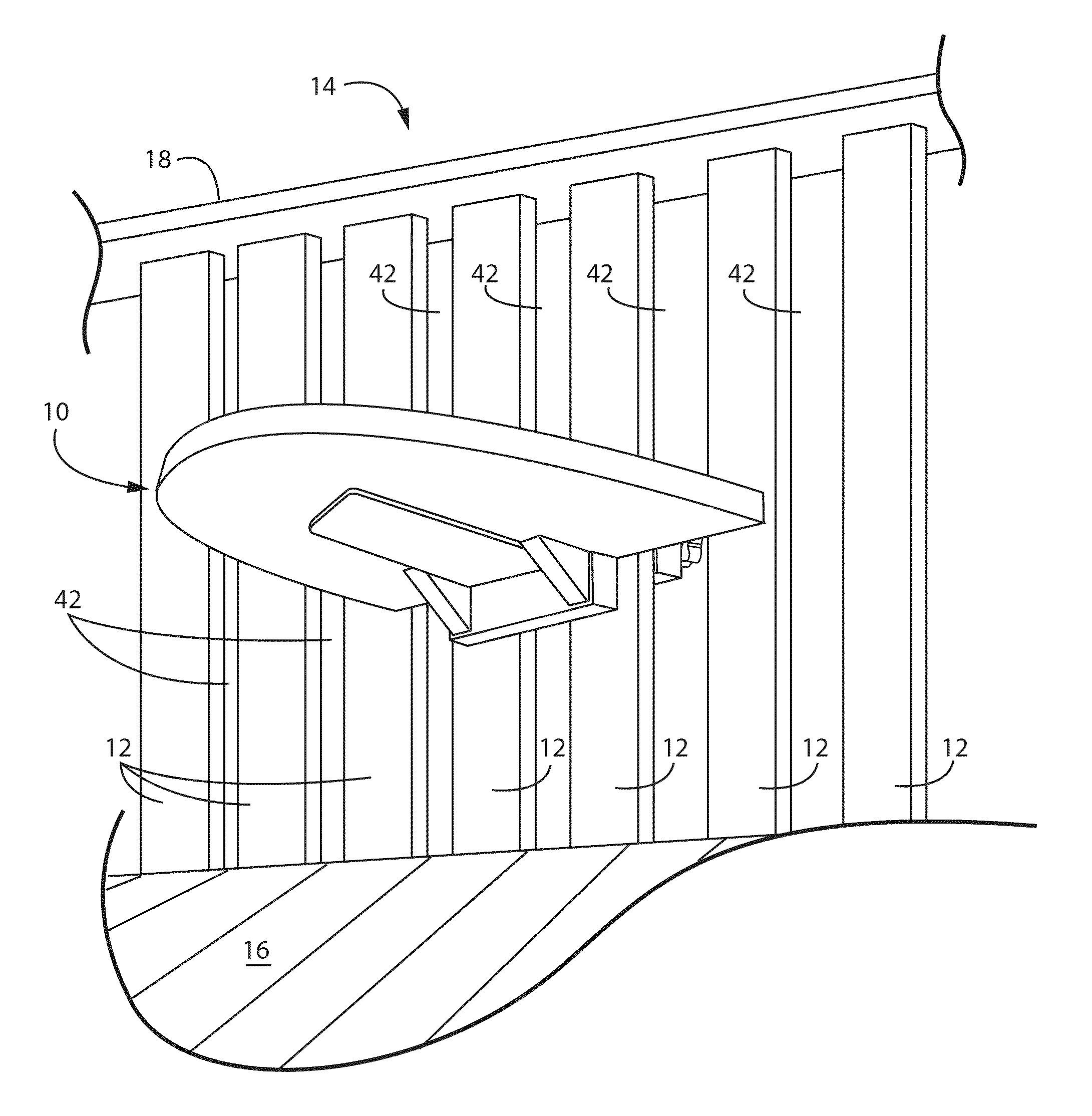
[0019]Referring now in detail to the drawing figures, wherein like reference numerals represent like parts throughout the several views, one embodiment of a table constructed according to the present disclosure is illustrated generally at 10 in FIG. 1. The table 10 is secured to at least one, and preferably two or more vertical posts 12, such as those forming a part of a ledge or railing 14 positioned around the periphery of a deck 16. The posts 12 are connected to one another at the bottom end by the deck 16 and at the top end by a hand rail 18.

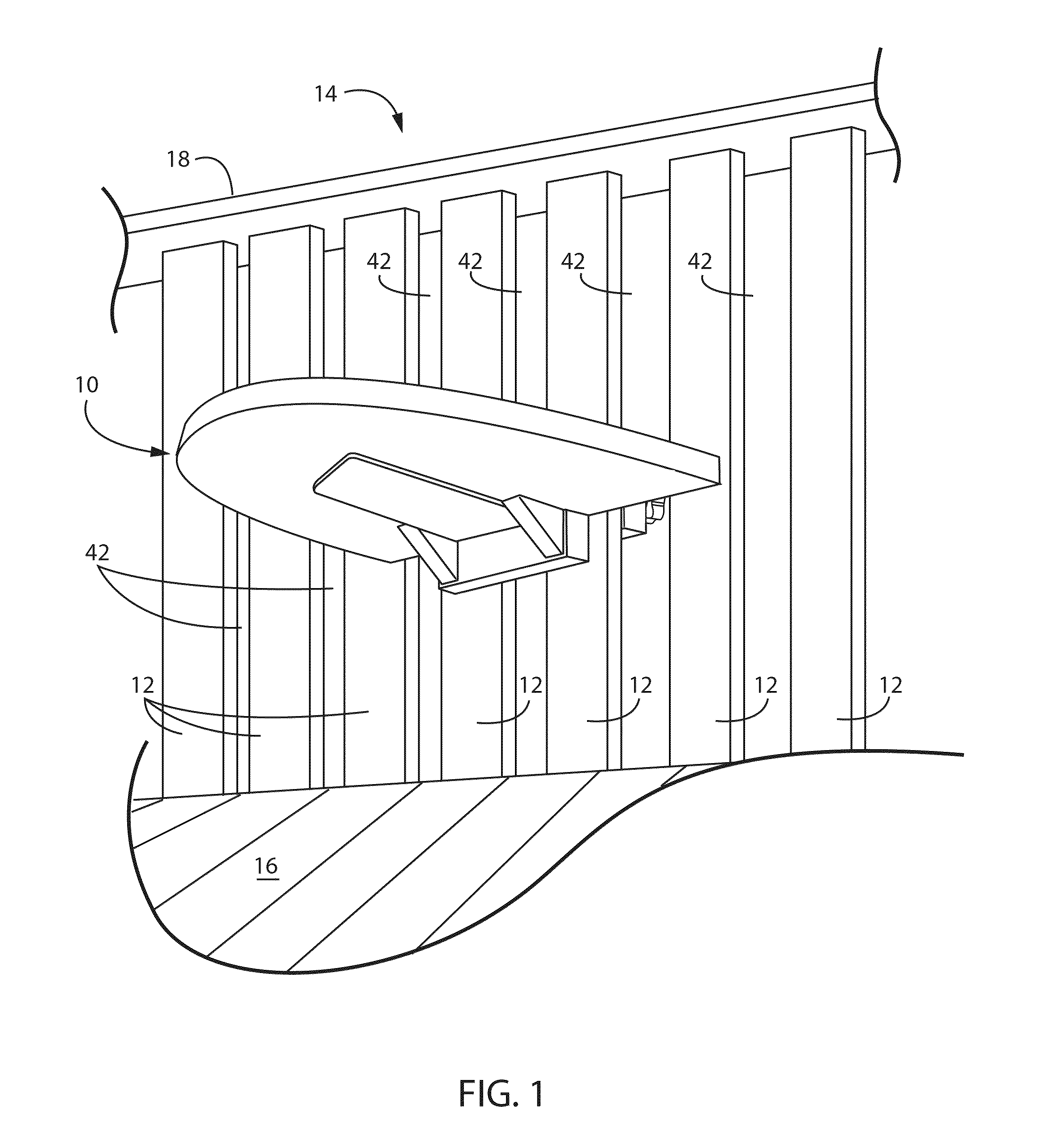
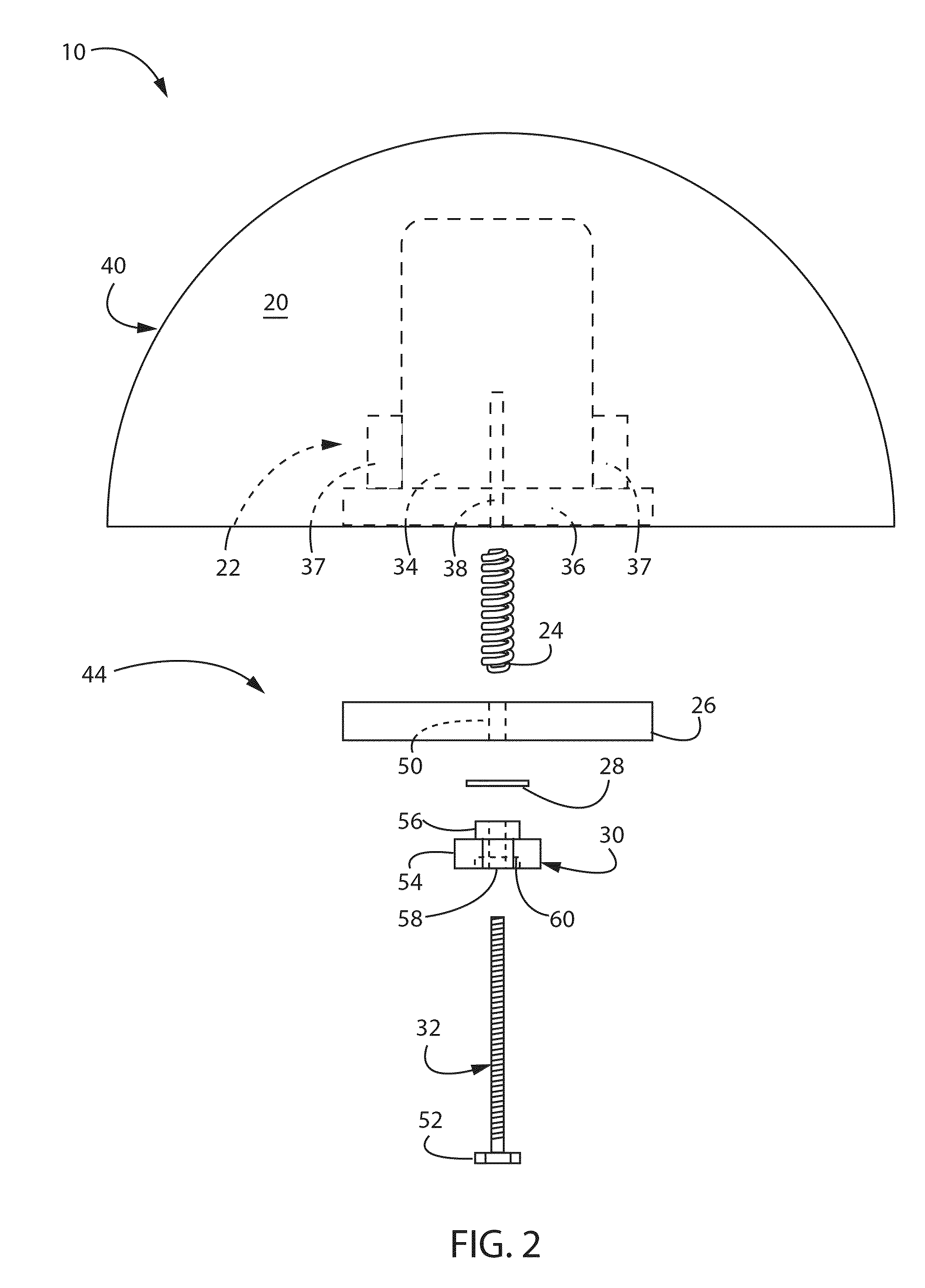
[0020]Referring now to FIGS. 2-5, the table 10 includes a table section 40, comprised of a support surface 20 and a bottom support 22. The table portion 40 can be formed of any suitable material, such as a plastic, wood or metal. The bottom support 22 includes a flat portion 34 secured to the support surface 20 and a projecting portion 36 attached to the flat portion 34 and extending downwardly from the support surface 20. The bottom support...


PUM

PropertyMeasurementUnit
areaaaaaaaaaaa
surface areaaaaaaaaaaa
forceaaaaaaaaaa

Abstract

A deck table is provided that includes a table section and a clamping mechanism that are attachable to a number of vertical posts in order to position the support surface on the posts in a horizontal position. The table section includes support surface and a bottom support that can be positioned against the posts and engaged by the clamping mechanism that extends between the posts. The clamping mechanism is rotatably attached to the table section and can be releasably engaged with the vertical posts to enable the table to be readily repositioned and / or removed from the posts, as desired, without disassembly of the component parts of the table.

Description

CROSS-REFERENCE TO RELATED APPLICATIONS[0001]This application claims priority from U.S. Provisional Application Ser. No. 61 / 524,837, filed on Aug. 18, 2011, the entirety of which is hereby expressly incorporated by reference herein.FIELD OF THE DISCLOSURE[0002]The present invention relates generally to a support surface in the form of a table, and more particularly to a table adapted for use on a deck.BACKGROUND OF THE DISCLOSURE[0003]There are many types of tables and other support surfaces that are used to hold objects at desired positions and locations. The vast majority of these tables are free-standing, in that the tables are supported by legs or other support members extending downwardly from the table top into contact with a floor or other surface to hold the table top at the desired location.[0004]However, in certain environments there is a limited amount of space on a surface upon which to support a table. In these environments, tables have been developed that minimize the ...

Claims


Application Information

Patent Timeline
Patent Type & Authority Patents(United States)
IPC IPC(8): A47B37/00
CPCA47B5/00Y10T29/49826
Inventor RAML, JOSEPH P.
Owner RAML JOSEPH P
Why Eureka
Try Eureka