Underground storage tank

Active Publication Date: 2013-10-22
AMERICAN WELDING & TANK LLC
View PDF6 Cites 8 Cited by
  • Summary
  • Abstract
  • Description
  • Claims
  • Application Information

AI Technical Summary

Problems solved by technology

Thus, if the withdrawal line is damaged to the point that it is ruptured, the gaseous fuel within the vessel assembly will pass through the plenum and escape through the rupture in the outer shell.

Method used


Image

  • Underground storage tank
  • Underground storage tank
  • Underground storage tank

Examples


Embodiment Construction

[0015]As used herein, “coupled” means a link between two or more elements, whether direct or indirect, so long as a link occurs.

[0016]As used herein, “attached” means that two elements are directly in contact with each other.

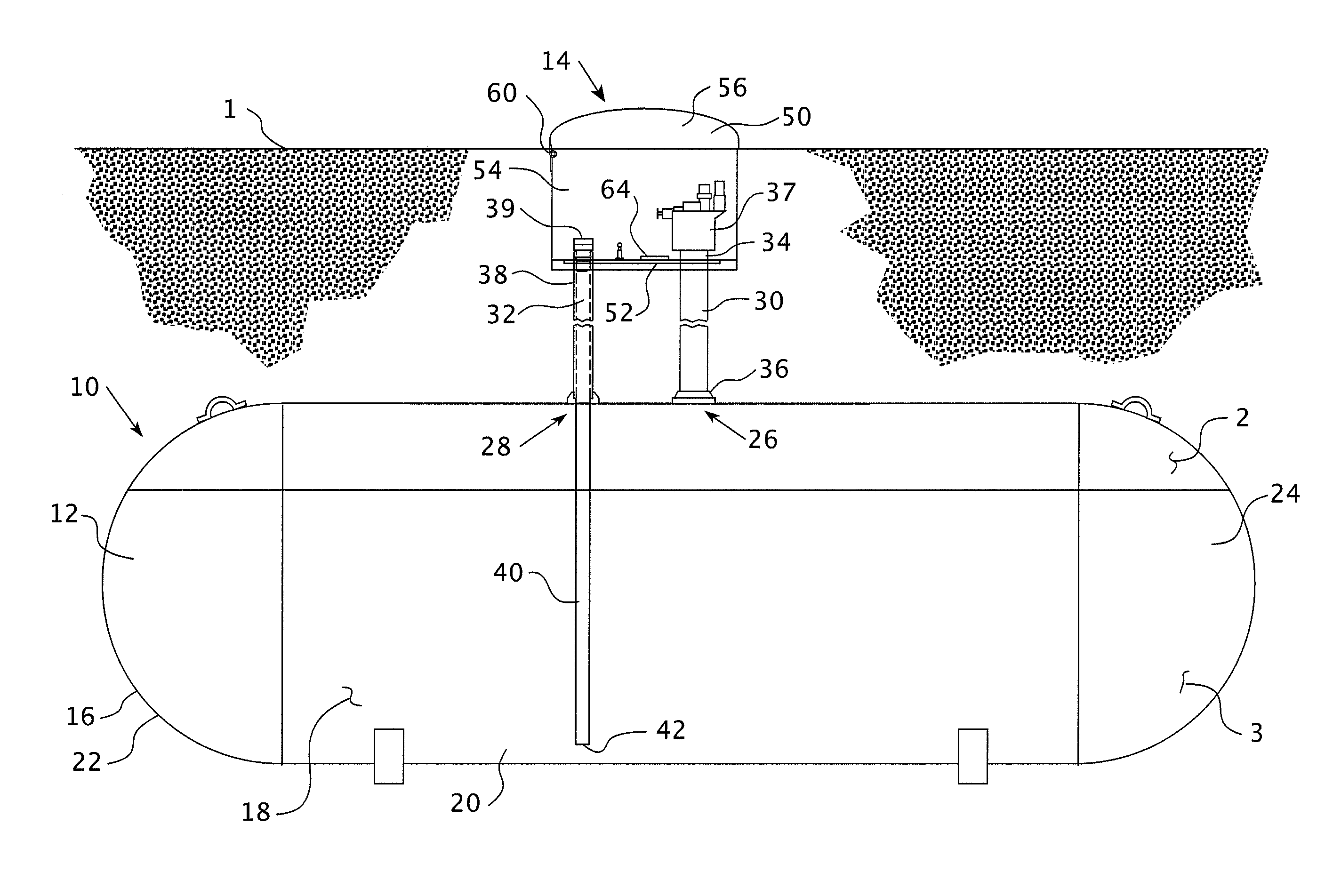
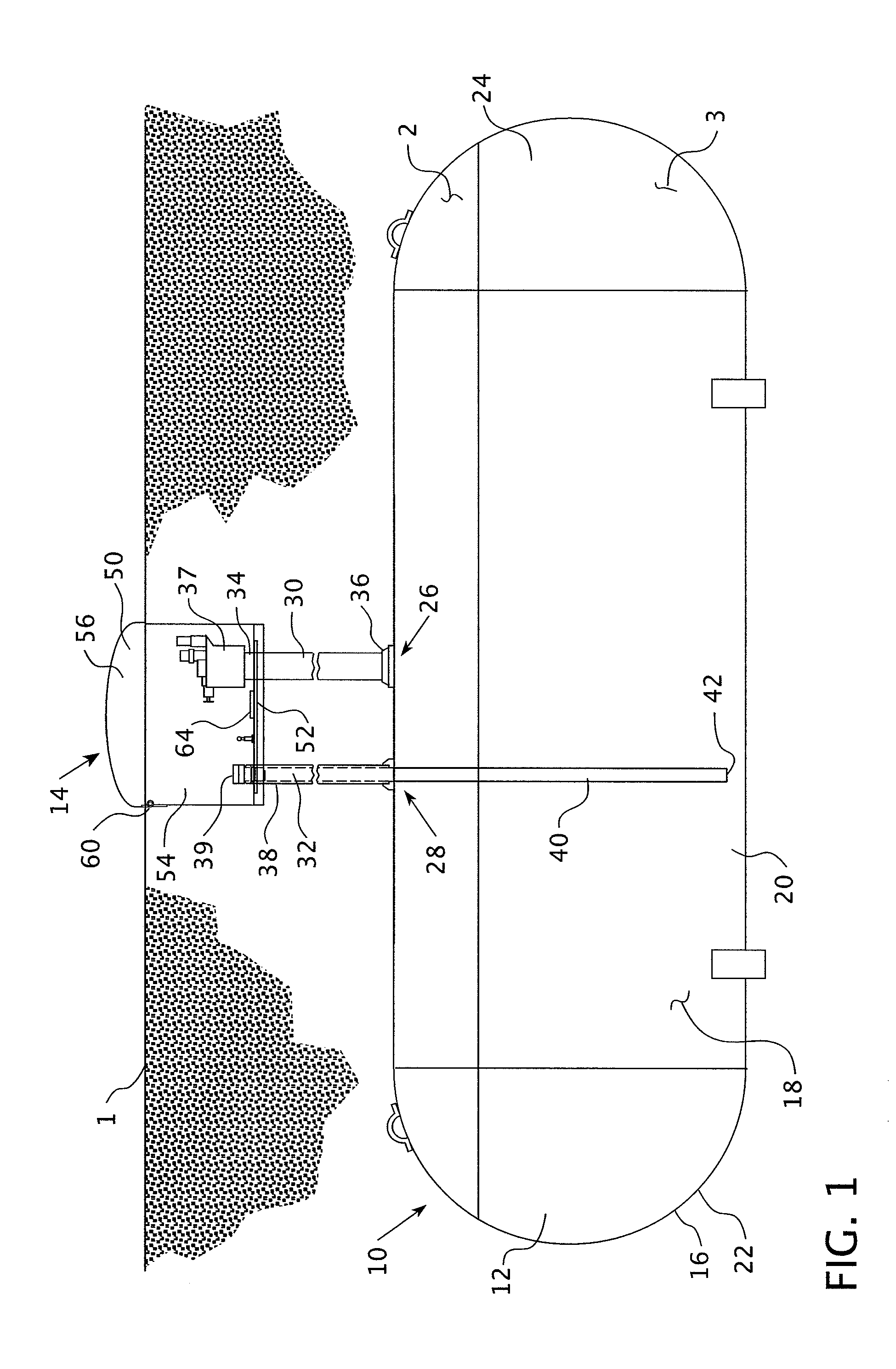
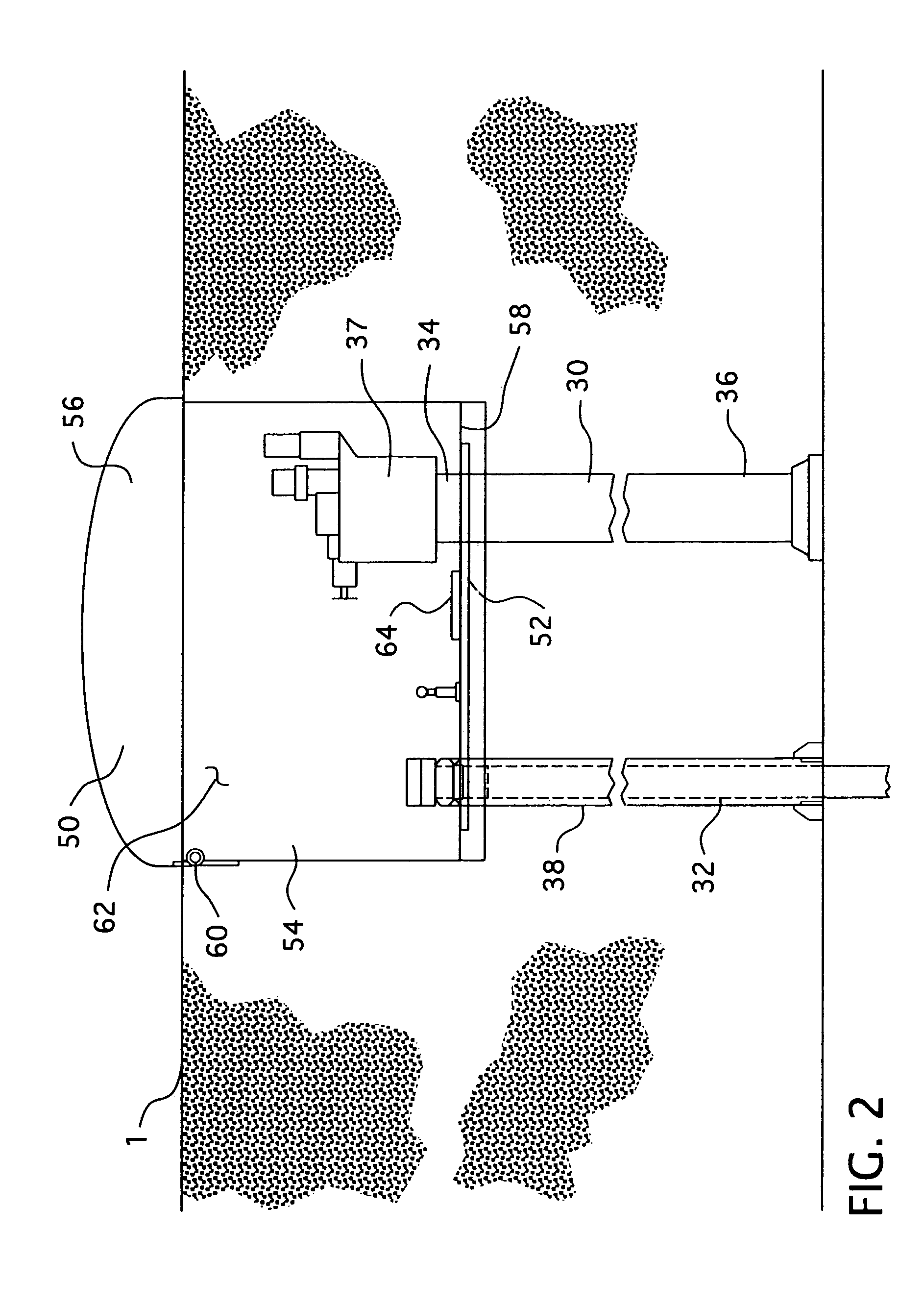
[0017]As shown in FIG. 1, an underground tank 10 includes a vessel assembly 12 and an access assembly 14. The vessel assembly 12 includes a sidewall 16 defining an enclosed space 18. While the vessel assembly 12 may have any shape, the vessel assembly sidewall 16, preferably, includes an elongated cylindrical portion 20 and two hemispherical end portions 22, 24. The longitudinal axis of the vessel assembly 12 extends generally horizontally under a ground surface 1. The vessel assembly sidewall 16 has, preferably, only two openings; a fuel line opening 26 and a withdrawal line opening 28, both of which are disposed at the top of the cylindrical portion 20. The vessel assembly 12 is structured to contain a fuel, such as, but not limited to, propane. The fuel is ty...


PUM


Abstract

The present invention provides an underground tank having a vessel assembly and a generally spaced access assembly. That is, the access assembly includes a fuel line, a withdrawal line, and a dome assembly. The fuel line and the withdrawal line have a first end disposed outside the vessel assembly and a second end disposed adjacent to or within the vessel assembly. The first end extends upwardly from the vessel assembly toward the ground surface. The dome assembly is coupled adjacent to the fuel and withdrawal line first end. As such, the vessel assembly may be buried at any depth as the fuel and withdrawal lines may have any length.

Description

BACKGROUND OF THE INVENTION[0001]1. Field of the Invention[0002]This application relates to an underground storage tank having an access dome assembly and, more specifically, an underground storage tank wherein the access dome assembly is raised above the bulk of the underground storage tank.[0003]2. Background Information[0004]Underground storage tanks may be used for storing fuel, such as, but not limited to, propane which is used for heat within a home or business. The tanks include a sidewall defining an enclosed space in which the fuel is stored. The sidewall is typically an elongated cylinder having two hemispherical end lids. Such tanks are typically buried about one to two feet under the ground surface with the longitudinal axis extending generally horizontal. The tanks also typically include an access assembly having a fuel line, a withdrawal line and a dome assembly. The dome assembly extends upward from the tank and protrudes slightly above the ground surface. Within the ...

Claims


Application Information

Patent Timeline
Patent Type & Authority Patents(United States)
IPC IPC(8): F16K24/00B67D7/78
CPCB65D90/105B67D7/78Y10T137/6995Y10T137/86332
Inventor OGDEN, WALKER LOUISLARSON, MICHAEL LILLEGAARDHUFFMAN, MICHAELFABRICY, DONALD FRANK
Owner AMERICAN WELDING & TANK LLC
Why Eureka
Try Eureka