Pressure sensor venting system

a pressure sensor and venting system technology, applied in liquid/fluent solid measurement, instruments, machines/engines, etc., can solve the problems of condensation, inconvenient venting, and inability to accurately measure the actual atmospheric pressure within the liquid container, so as to achieve efficient and accurate liquid level measurement

Active Publication Date: 2013-10-29
S J ELECTRO SYST INC
View PDF8 Cites 2 Cited by
  • Summary
  • Abstract
  • Description
  • Claims
  • Application Information

AI Technical Summary

Benefits of technology

[0010]A system for efficiently and accurately measuring a liquid level. The invention generally relates to a pressure transducer which includes a housing, a pressure transducer within the housing, a diaphragm, a pressure passage fluidly connecting the pressure transducer and a pressurized liquid from the diaphragm, and a first vent tube that is fluidly connected to the pressure transducer opposite of the pressure passage. The distal end of the first vent tube extends outwardly from the housing and extends a distance into a second vent tube. The second vent tube is fluidly connected to liquid resistant vent that is positioned within the interior space of the liquid container and above the liquid level.

Problems solved by technology

One of the main problems with convention fluid pressure transducers is venting the pressure transducer to get a true atmospheric reading in the liquid container.
One problem with venting a pressure transducer is getting liquid inside of the venting resulting in inaccurate readings.
Another problem with venting a pressure transducer is that the current solution is to vent the pressure transducer outside of the liquid container and in the junction box, however this results in an atmospheric pressure that can be significantly different from what the true atmospheric pressure is within the liquid container.
In addition, temperature differences between the interior and exterior of the tank can cause condensation to incur within the vent.

Method used


Image

  • Pressure sensor venting system
  • Pressure sensor venting system
  • Pressure sensor venting system

Examples


Embodiment Construction

A. Overview.

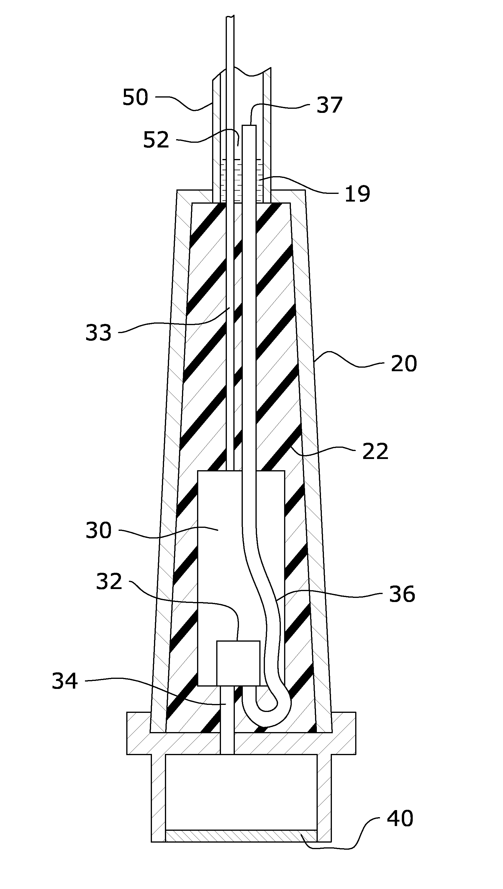
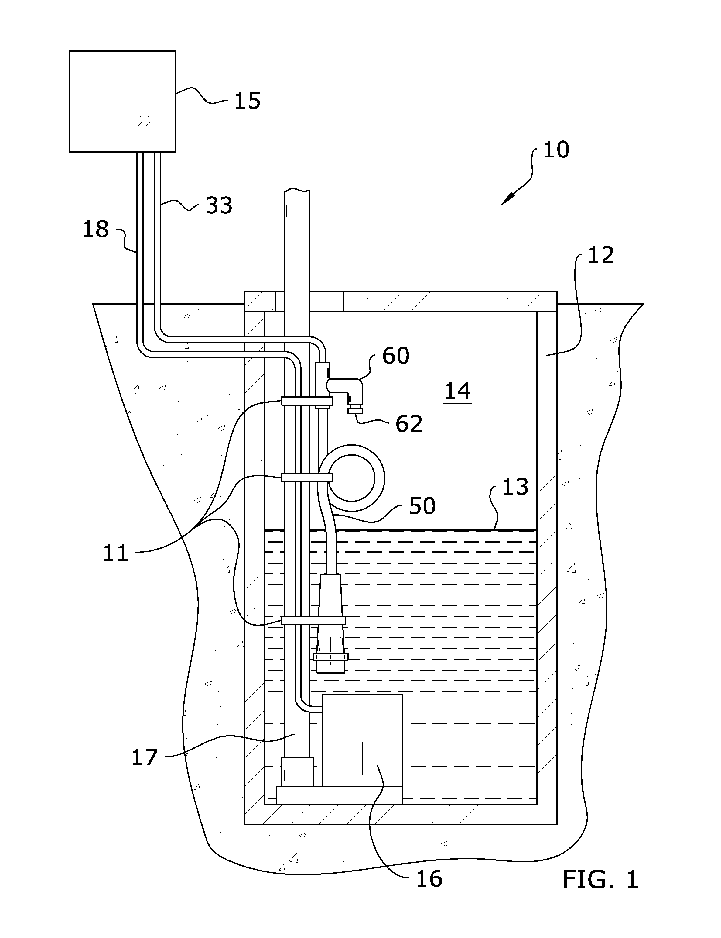
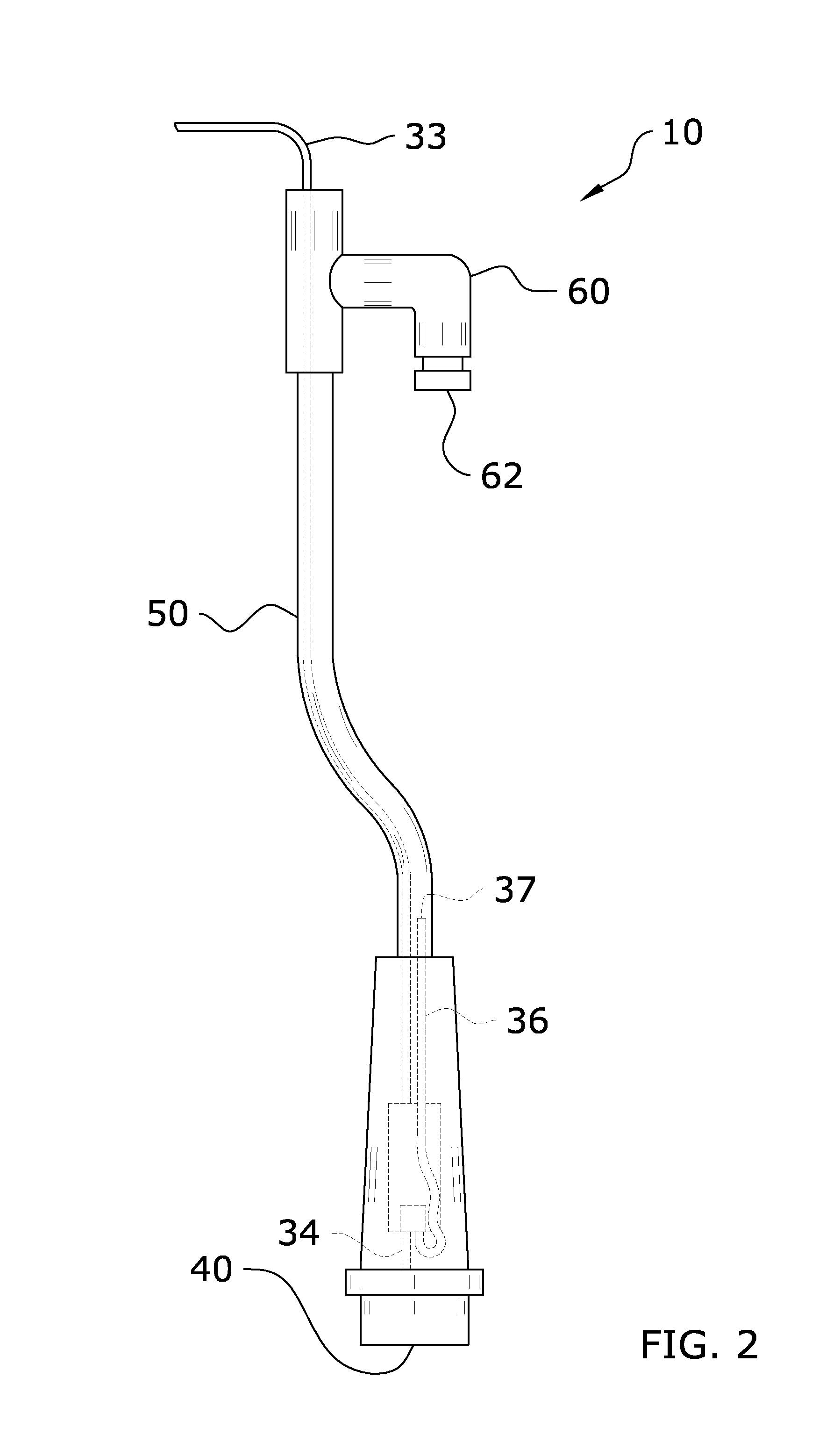
[0017]Turning now descriptively to the drawings, in which similar reference characters denote similar elements throughout the several views, FIGS. 1 through 3b illustrate a pressure sensor venting system 10, which comprises a housing 20, a pressure transducer 32 within the housing 20, a diaphragm 40, a pressure passage 34 fluidly connecting the pressure transducer 32 and a pressurized liquid from the diaphragm 40, and a first vent tube 36 that is fluidly connected to the pressure transducer 32 opposite of the pressure passage 34. The distal end 37 of the first vent tube 36 extends outwardly from the housing 20 and extends a distance into a second vent tube 50. The second vent tube 50 is fluidly connected to liquid resistant vent 60 that is positioned within the interior space 14 of the liquid container 12 and above the liquid level 13.

B. Exemplary Liquid Container.

[0018]FIG. 1 illustrates an exemplary liquid container 12 comprised of a septic tank suitable for usage with...


PUM


Abstract

A pressure sensor venting system for efficiently and accurately measuring a liquid level. The pressure sensor venting system generally includes a housing, a pressure transducer within the housing, a diaphragm, a pressure passage fluidly connecting the pressure transducer and a pressurized liquid from the diaphragm, and a first vent tube that is fluidly connected to the pressure transducer opposite of the pressure passage. The distal end of the first vent tube extends outwardly from the housing and extends a distance into a second vent tube. The second vent tube is fluidly connected to liquid resistant vent that is positioned within the interior space of the liquid container and above the liquid level.

Description

CROSS REFERENCE TO RELATED APPLICATIONS[0001]I hereby claim benefit under Title 35, United States Code, Section 119(e) of U.S. provisional patent application Ser. No. 61 / 340,087 filed Mar. 11, 2010. The 61 / 340,087 application is currently pending. The 61 / 340,087 application is hereby incorporated by reference into this application.STATEMENT REGARDING FEDERALLY SPONSORED RESEARCH OR DEVELOPMENT[0002]Not applicable to this application.BACKGROUND OF THE INVENTION[0003]1. Field of the Invention[0004]The present invention relates generally to a submersible pressure transducer and more specifically it relates to a pressure sensor venting system for efficiently and accurately measuring a liquid level.[0005]2. Description of the Related Art[0006]Any discussion of the related art throughout the specification should in no way be considered as an admission that such related art is widely known or forms part of common general knowledge in the field.[0007]Fluid pressure transducers are utilized ...

Claims


Application Information

Patent Timeline
Patent Type & Authority Patents(United States)
IPC IPC(8): G01F23/00
CPCG01L19/0645G01L19/149
Inventor BERGUM, ALAN J.
Owner S J ELECTRO SYST INC
Why Eureka
Try Eureka