
Apparatus for occipital-cervical fixation enabling supplemental occipital bone fixation

a technology of occipital cervical spine and appendix, which is applied in the field of medical treatments, can solve the problems of inability to attach existing rigid plates and rods to the back of the skull (occiput), inability to stabilize the upper cervical spine with occipital bone, and inability to achieve bone fusion/fixation. , to achieve the effect of optimizing bone fusion/fixation and reducing the profil

Inactive Publication Date: 2013-10-29
UNIV OF SOUTH FLORIDA
View PDF21 Cites 13 Cited by
  • Summary
  • Abstract
  • Description
  • Claims
  • Application Information

AI Technical Summary

Benefits of technology

This solution provides a more rigid and stable biomechanical construct for occipito-cervical fusion, reducing the risk of hardware failure and allowing for stabilization without the need for rigid fixation or multiple occipital attachment points, thus offering a reliable alternative to conventional methods.

Problems solved by technology

The medical treatments heretofore known that relate to stabilization of the upper cervical spine are limited by poor occipital bone purchase and multiple attachment points for screws with subsequent construct failure at the cranio-cervical junction.
However, in some cases the back of the skull (occiput) is unsuitable for attaching existing rigid plates and rods.
For example, when suboccipital craniectomy has been performed there is no occipital bone available to which connections for stabilization can be made.
Moreover, the known upper cervical spine stabilization systems use rather long, contoured rods that need to be contoured in the operating room.
Such rods are subject to failure due to large bending forces.
The variable regional bone thickness of the occiput, combined with the location of the dural sinuses, limits the placement and length of occipital screws, thus potentially affecting construct strength and rigidity.
The optimal placement of screws in the occipital bone is technically demanding and in cases where suboccipital craniectomy is performed the area available for hardware placement is even more restricted.

Method used


Image

  • Apparatus for occipital-cervical fixation enabling supplemental occipital bone fixation
  • Apparatus for occipital-cervical fixation enabling supplemental occipital bone fixation
  • Apparatus for occipital-cervical fixation enabling supplemental occipital bone fixation

Examples


Embodiment Construction

[0032]Embodiments of the present invention relate to stabilization of the upper cervical spine. In particular, embodiments of the present invention provide an apparatus and method for stabilization of a head to a neck joint.

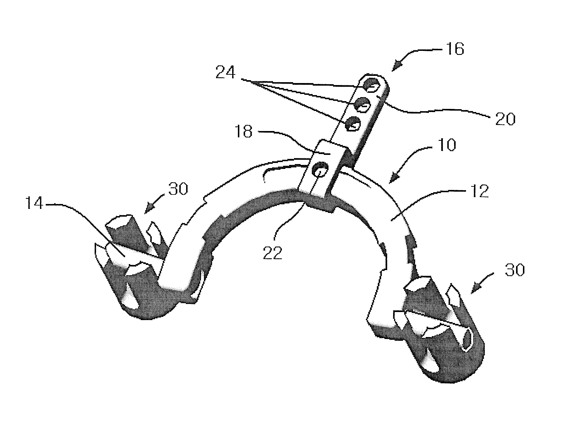
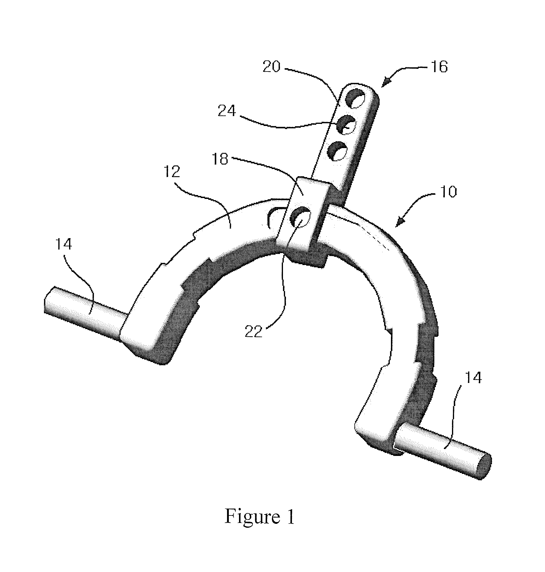
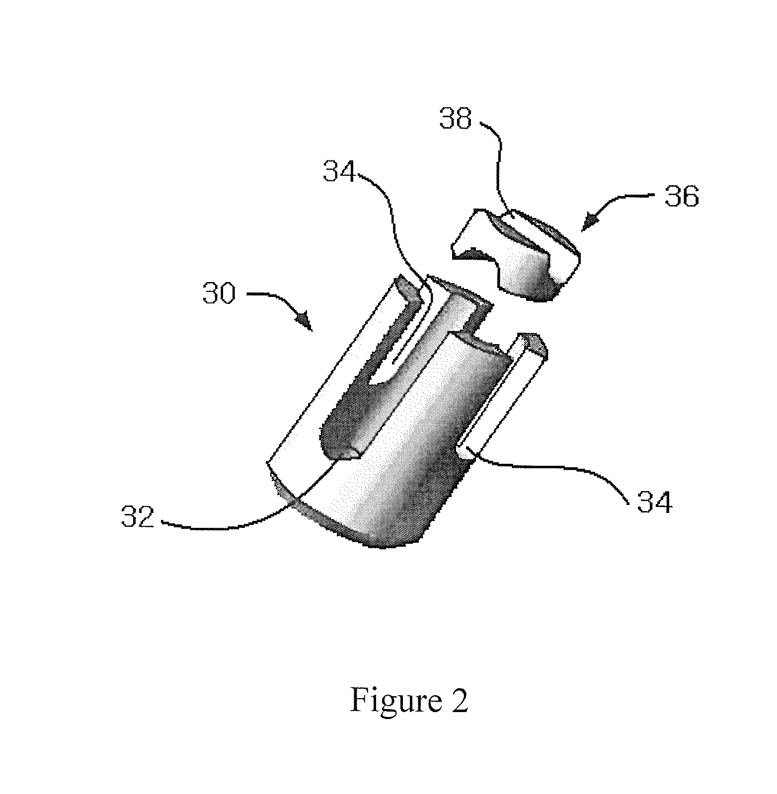
[0033]In accordance with an embodiment of the present invention, an apparatus for stabilization of the upper cervical spine is provided having a structure that includes three main parts. The first part can be referred to as a base, the second part can be referred to as an occiput attachment, and the third part can be referred to as a polyaxial screw.

[0034]Referring first to FIG. 1, it will there be seen that the first main part can be a rigid occi-cervical base member, denoted 10 as a whole. Base 10 includes “C”-shaped central part 12 and a pair of rigid attachment rods, collectively denoted 14, that extend transversely outwardly at respective free ends of said “C”-shaped occi-cervical central part. The occi-cervical base member can be a plate or crosslink.

[0035]...


PUM


Abstract

An apparatus for stabilization of a patient's head relative to the patient's neck joint includes an occi-cervical base member having a shaped “C”-shaped central part and first and second attachment rods respectively connected to and extending transversely from free ends of the central part. An occiput attachment has a first end slideably engaged to the central part and a flat, straight second end that extends radially outwardly relative to the first end. First and second polyaxial screw heads are adapted to be implanted in first and second occipital condyles of a patient, respectively. The first and second polyaxial screw heads are adapted to engage first and second stabilizing rods, respectively, that are placed in-line with the cervical spine of a patient and to engage the first and second attachment rods, respectively.

Description

CROSS-REFERENCE TO RELATED APPLICATIONS[0001]This application is the U.S. national stage application of International Patent Application No. PCT / US2008 / 085154, filed Dec. 1, 2008, which claims the benefit of U.S. provisional application Ser. No. 60 / 990,987, filed Nov. 29, 2007, which are hereby incorporated by reference in their entirety.FIELD OF THE INVENTION[0002]This invention relates to medical treatments. More particularly, it relates to an apparatus that enables stabilization of the upper cervical spine with occipital condyle screws and a base member for holding the screws.BACKGROUND[0003]The medical treatments heretofore known that relate to stabilization of the upper cervical spine are limited by poor occipital bone purchase and multiple attachment points for screws with subsequent construct failure at the cranio-cervical junction. Conventional systems for providing more reliable stabilization of the head to the neck joint rely on attachment from the neck to the back of the ...

Claims


Application Information

Patent Timeline
Patent Type & Authority Patents(United States)
IPC IPC(8): A61B17/56
CPCA61B17/7055A61B17/7002
Inventor URIBE, JUAN S.JOHNSON, WESLEY M.
Owner UNIV OF SOUTH FLORIDA
Learn More