Solid state lighting control device

a control device and solid-state technology, applied in lighting devices, lighting sources, electrical equipment, etc., can solve the problems of legacy dimmers not working, the color of emitter changes with age, and the short life of led lamps, so as to eliminate or isolate the dangers of ac power distribution, eliminate or isolate the dangers of centralized heat concentration

Inactive Publication Date: 2016-11-24
ATX LED INC
View PDF6 Cites 1 Cited by
  • Summary
  • Abstract
  • Description
  • Claims
  • Application Information

AI Technical Summary

Benefits of technology

[0007]The intended outcome benefits of this solid state lighting control device invention to a solid state lighting system in general are the elimination of centralized heat concentrations at each singular solid state lighting lamp, reduced wire sizes in the wiring distribution complexity and there installed wiring cost, creation of a singular centralized control point distribution location for solid state lighting drivers who's location is similar in use to traditional Legacy system locations, and to eliminate or isolate the dangers of AC power distribution to solid state emitter lighting fixtures. Additional intended outcomes of separating the heat conducting parts of a solid state lighting emitter from the solid state lighting control and driver circuitry are the reduction of the size and requirement of heat sinking at the solid state lighting emitters therefore extending the life of the solid state lighting emitters, plus as an additional benefit will be to provide for the reduction in size of the solid state lighting fixture housings or enclosures. Although there is only a small reduction in overall system heat the thermal isolation of components allows more natural cooling without highly designed engineering and connected thermal auxiliary cooling components.

Problems solved by technology

Problems arose from this initial design.
First, heat from the driver, AC to DC voltage conversion, and the Emitter caused a short life of the LED lamp.
Second, the emitter color changed with age, mostly caused by the heat, Third, Legacy dimmers did not function because they did not work with the zero voltage crossing of AC and the reduced voltage at low lighting levels was below what the driver would output to the emitter.
The next generation of solid state lighting into Legacy systems progressed with dimmers modified to address the voltage issues (and other technical improvements), and Legacy LED lamps with greater heat dissipating capacity but this just improved existing integration issues.
Heat and other existing issues still exist.
And heat and other existing issues still exist.
Many inefficacies and redundancies exist in the current Legacy solid state lighting systems today.

Method used


Image

  • Solid state lighting control device
  • Solid state lighting control device
  • Solid state lighting control device

Examples


Embodiment Construction

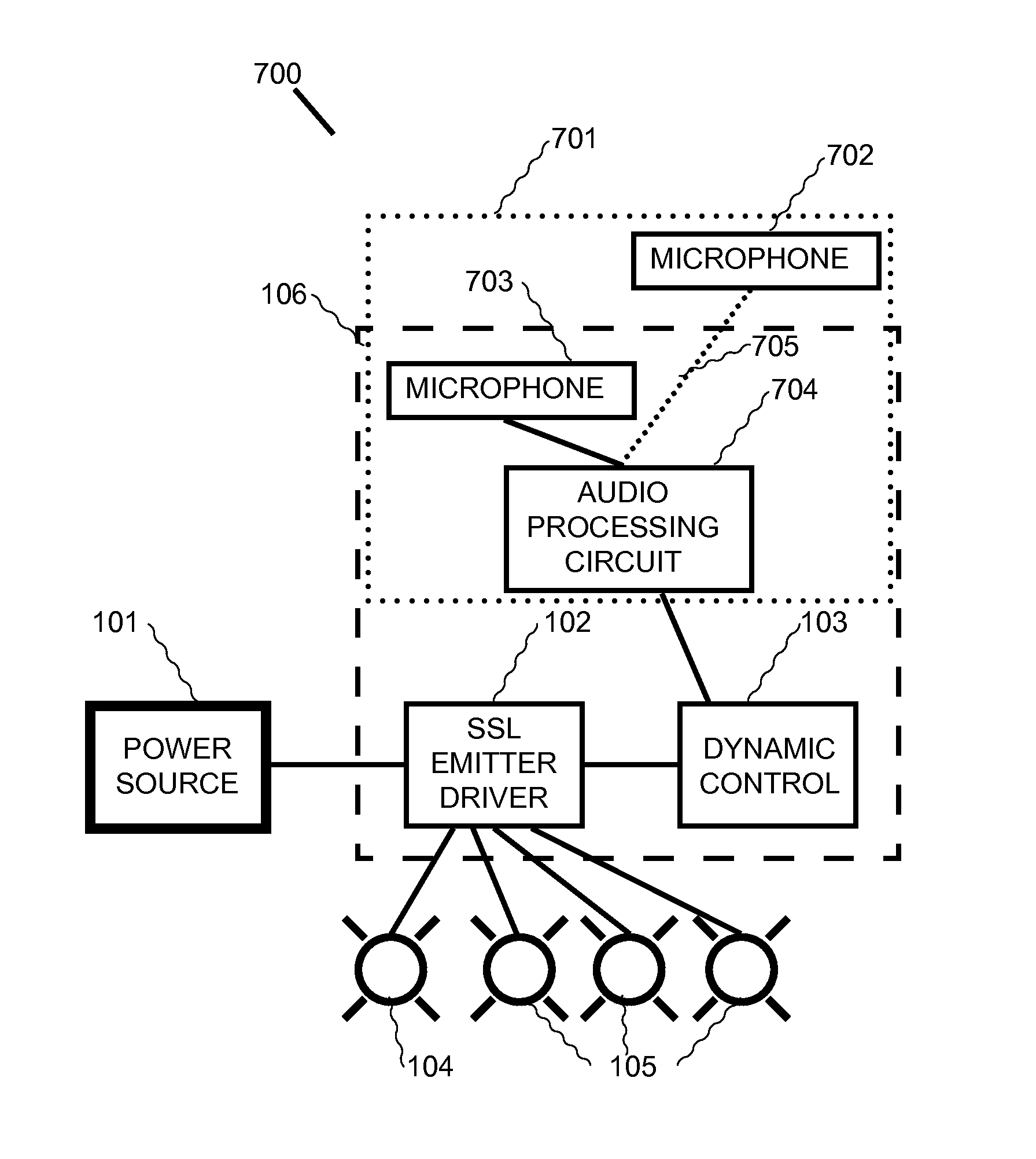
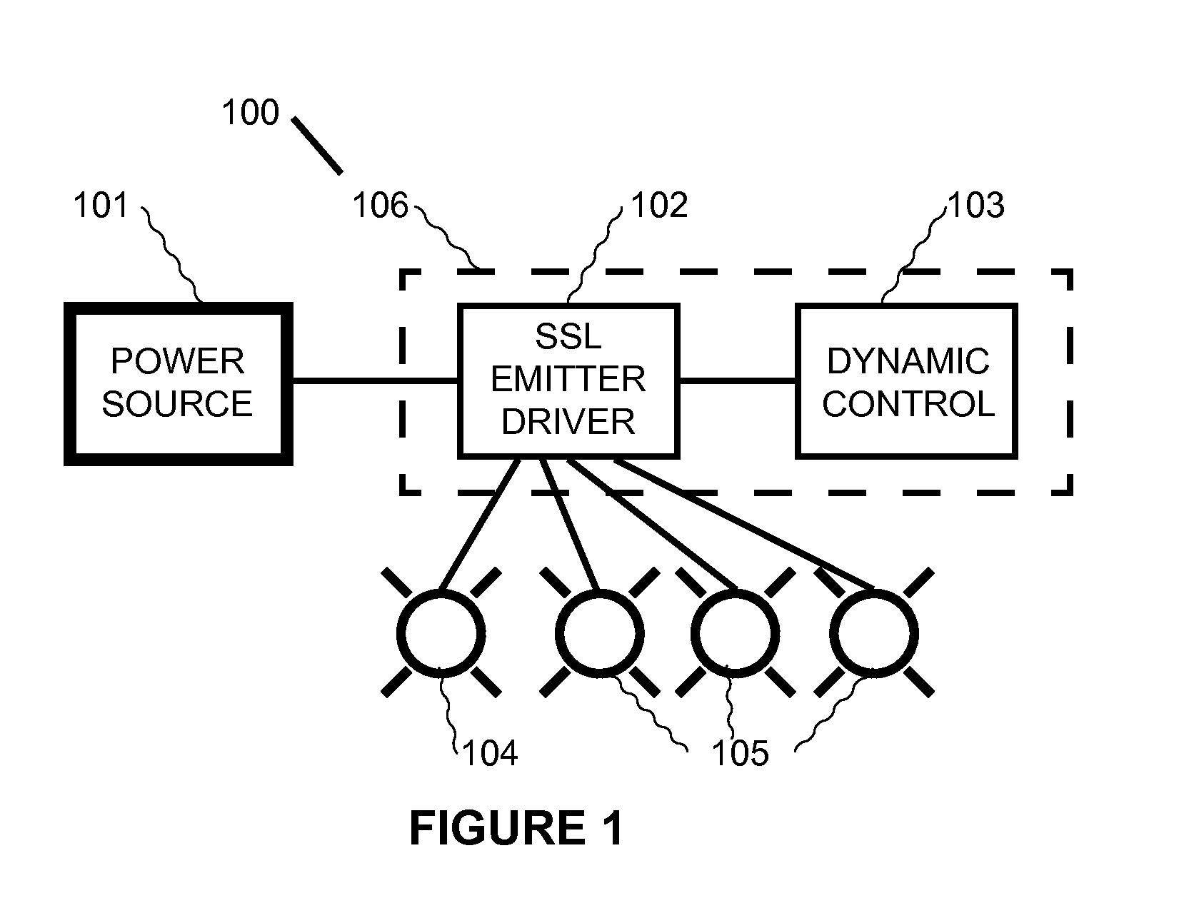
[0030]Since Direct Current (DC) distribution for solid state lighting emitters is not standard or common in building structures today the following embodiments of this invention may require a fundamental shift in how building structures are wired. In this embodiments, the solid state lighting control device (100, 1100) may include in a enclosure or housing (106). Where such enclosure or housing may be located (2101, 2201) to provide user input (401, 1401) or functionality selections to a control circuit (103, 1103) that may interoperate user inputs (401, 501, 1401, 1501) and then may process a logic schema, code or program or timer function that may output a desired digital or analog circuit that may emulate a function or required input variable which may be a relay, gate, field effect transistor, electronic switch, variable or selectable voltage circuit, variable or selectable current circuit, variable or selectable resistance, or other specific input variable (401, 501, 704, 804, ...


PUM


Abstract

Methods and systems are provided for the control of solid state lighting as applied to general illumination environments, architectural, and accent lighting. The invention as detailed provides a system according to some embodiments that includes a dynamic controller that provides control signals to a solid state lighting driver or multiple drivers at the location where the user interface for said control is located and that are configured to provide 0 and 100 per cent of maximum brightness control to one or multiple separately located solid state lighting emitters enclosed in what could be called a light fixture or fixtures.

Description

FIELD OF THE INVENTION[0001]The present invention relates to solid state lighting, particularly, the control of solid state light emitter fixtures.BACKGROUND OF THE INVENTION[0002]The design and invention of general illumination lighting derived from electricity began in the late 1,800.s, and was popularized by inventors Tesla and Edison and commercialized by Westinghouse and General Electric. This original system provided for the distribution of alternating current and it's connection to a filament lamp controlled by a blade switch. This system has progressed over the last about 130 years, but in general still maintains the same basis of distributing alternating current over physical wires, with the expansion of control from a single switch to dimmers to highly connected digitally connected devices, and the filament lamp to many styles of light emitting devices. This core system is commonly referred to a “Legacy” system, and is referred to as such throughout this.[0003]The large pr...

Claims


Application Information

Patent Timeline
Patent Type & Authority Applications(United States)
IPC IPC(8): H05B37/02
CPCH05B37/0227H05B37/0236H05B37/0245H05B47/12H05B47/19Y02B20/40
Inventor VIGEN, DREW FORREST
Owner ATX LED INC
Why Eureka
Try Eureka