Shielded surgical navigation system that determines the position and orientation of the tracked object with real and virtual dipoles

a navigation system and shield technology, applied in the field of system and method for determining the location of objects, can solve the problems of reducing the overall efficiency of the surgeon performing the procedure, and affecting the accuracy of the surgical procedur

Active Publication Date: 2013-10-29
STRYKER CORP
View PDF22 Cites 14 Cited by
  • Summary
  • Abstract
  • Description
  • Claims
  • Application Information

AI Technical Summary

Benefits of technology

[0024]The system of this invention allows the transmitter assembly to be moved relative to shield. Further this invention is constructed so that the transmitter can be placed relatively large distance away from the shield. Thus, use of this system in an operating room does not require installation of either a custom designed operating room table or the extensive reconfiguration of an existing operating room table.

Problems solved by technology

Nevertheless, there is a drawback associated with these systems.
If the breaking of a line-of-sight results in the interruption of the generation of the object position and location data, it may be necessary stop the procedure until the system can again provide the data.
Such delays reduce the overall efficiency of the surgeon performing the procedure.
Moreover, such delays can increase the overall length of time it takes to perform the procedure.
This added magnetic field thus introduces an error into the magnetic field measurements made by the sensor.
In the above system, the highly magnetic permeable plate itself is a source of interference.
However, because the transmitter and plate are at fixed relationship relative to their relative position and orientation, this interference can be calculated at system assembly.
A clear limitation of the above-described system is that it requires the transmitter to remain at a fixed location relative to the shielding plate.
This means the shielding could not be used with a system with a moving transmitter.

Method used


Image

  • Shielded surgical navigation system that determines the position and orientation of the tracked object with real and virtual dipoles
  • Shielded surgical navigation system that determines the position and orientation of the tracked object with real and virtual dipoles
  • Shielded surgical navigation system that determines the position and orientation of the tracked object with real and virtual dipoles

Examples


Embodiment Construction

I. Theoretical Foundation of Shield Effect

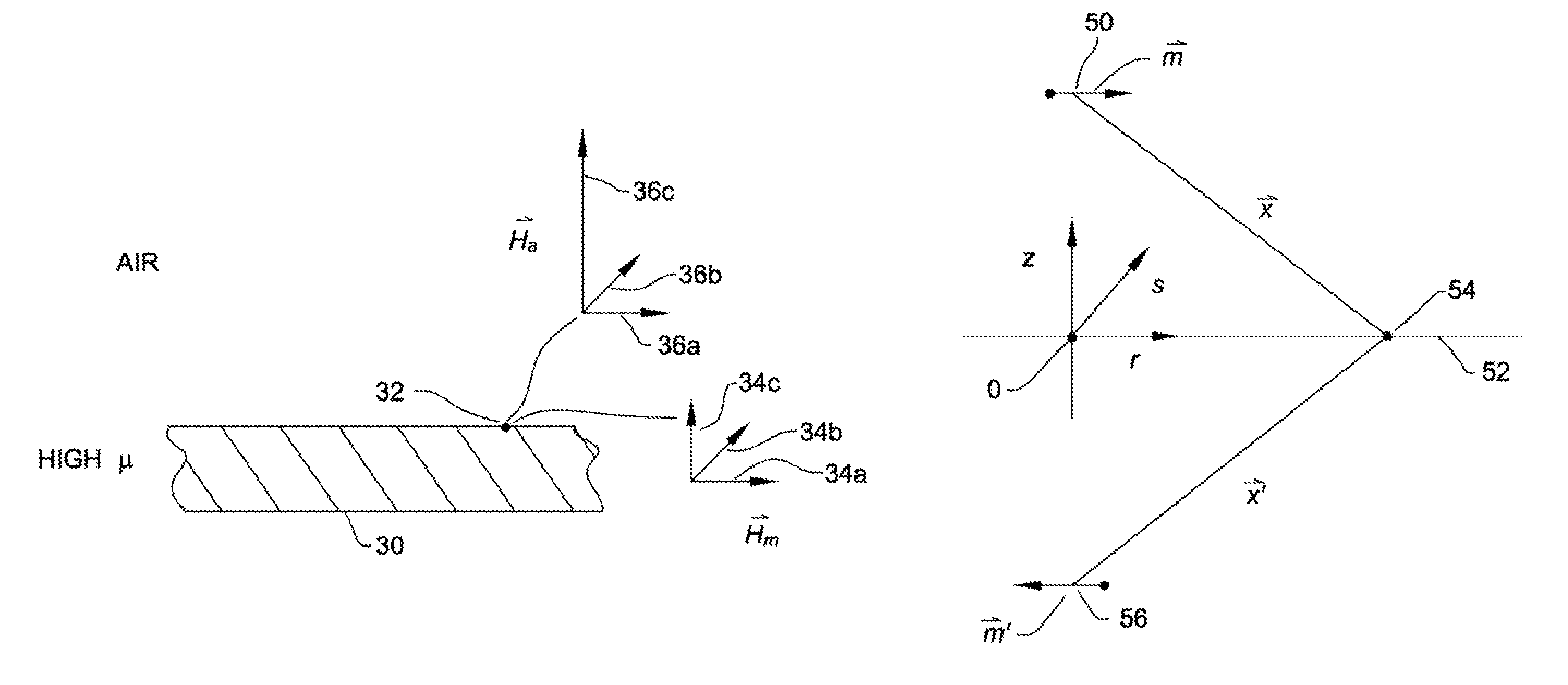
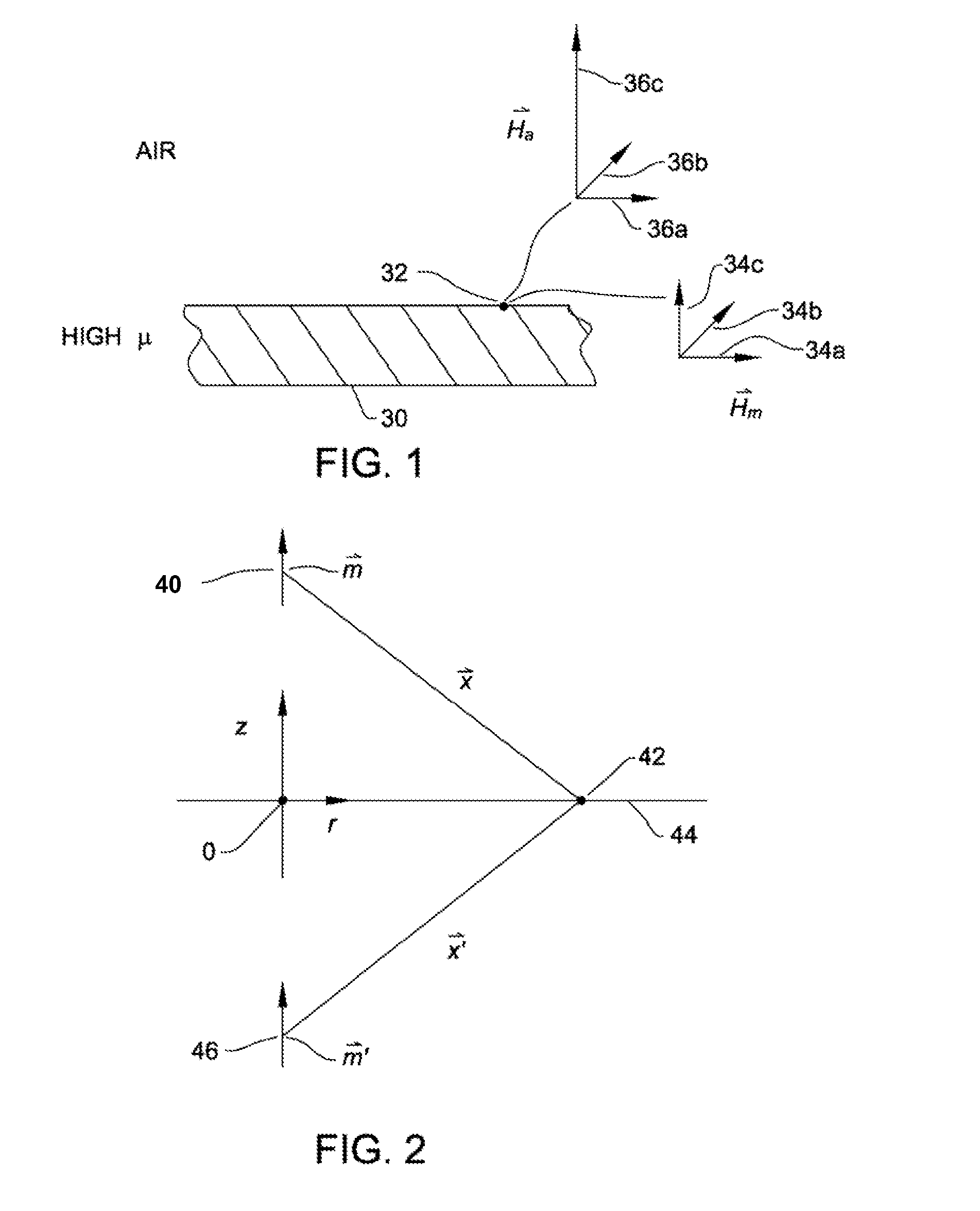
[0034]The system and method of this invention is understood by appreciating electromagnetic fields in the vicinity of a shield, a component having a high magnetic permeability, μ. FIG. 1 illustrates this environment. Here a shield 30 is formed from a metal having a high magnetic permeability such as steel. At the surface of shield 30, the boundary between the shield and the ambient environment, there is no current flow. Accordingly, at a point 32 at this interface:

({right arrow over (B)}S−{right arrow over (B)}A)·{right arrow over (n)}=0  (1)

and

({right arrow over (H)}S−{right arrow over (H)}A)×{right arrow over (n)}=0  (2)

Here, {right arrow over (B)}S and {right arrow over (B)}A are, respectively, the magnetic induction, flux density, of the shield 30 and air, respectively, at boundary point 32. Variables {right arrow over (H)}S and {right arrow over (H)}A are the strength of the magnetic field of, respectively, the shield and the air at the...


PUM


Abstract

A system for determining the position and orientation of a tracked object by measuring electromagnetic energy. The system includes a shield of magnetic permeable material positioned on one side of the object to be tracked. A transmitter emits the electromagnetic energy and there is a tracker sensor. One of the transmitter or tracker sensor is attached to the object to be tracked. A correction sensor is at fixed location relative to the transmitter assembly. Both sensors assemblies measure the electromagnetic energy emitted by the transmitter. Based on the energy measured by the correction sensor, the location of a virtual dipole that mirrors the transmitter, the real dipole, on the opposite side of the shield is determined. Based on the positions of the real and virtual dipoles and the energy measured by the tracker sensor, the position and orientation of the tracker sensor relative to the transmitter is determined.

Description

RELATIONSHIP TO EARLIER FILED APPLICATIONS[0001]This application is a continuation of PCT Application No. PCT / US2007 / 064753 filed 23 Mar. 2007 which claims priority from U.S. Provisional Patent Application No. 60 / 787,123 filed 29 Mar. 2009. The contents of the priority applications are explicitly incorporated herein by reference.FIELD OF THE INVENTION[0002]This invention is generally related to a system and method for determining the location of an object, such as the location of an object in a surgical field. More specifically, this invention is related to a system and method for determining the location of an object using electromagnetic radiation wherein a shield blocks the effects of a metal object that may be present.BACKGROUND OF THE INVENTION[0003]There are number of fields of human endeavor wherein it is useful, if not necessary, to know precisely the location and orientation of an object within a space. Surgery is one such field in which this information is desirable. Surgi...

Claims


Application Information

Patent Timeline
Patent Type & Authority Patents(United States)
IPC IPC(8): A61B5/05G01S19/07G01S19/04
CPCA61B19/52A61B19/5244G01B7/003A61B2019/5251A61B2019/5274A61B2019/5458A61B2019/5475A61B90/36A61B2034/2074A61B2090/3975A61B34/20A61B2034/2051A61B2090/3958
Inventor WU, CHUNWU
Owner STRYKER CORP
Why Eureka
Try Eureka