

Utility vehicle
a technology for utility vehicles and vehicles, applied in vehicle components, superstructure subunits, pedestrian/occupant safety arrangements, etc., can solve problems such as stones and wooden twigs being kicked up, and achieve the effects of simplifying the management of components, reducing the number of necessary components, and reducing the cost of fron
- Summary
- Abstract
- Description
- Claims
- Application Information
AI Technical Summary
Benefits of technology
Problems solved by technology
Method used
Image

Examples
first embodiment
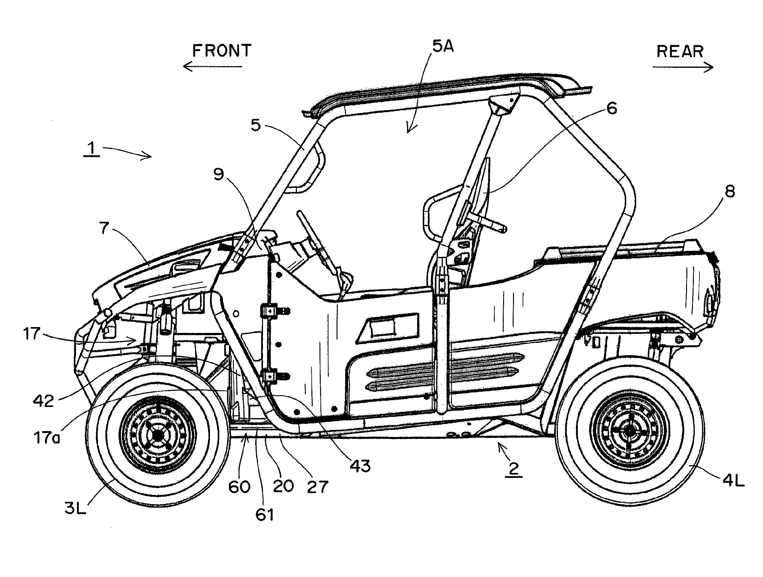
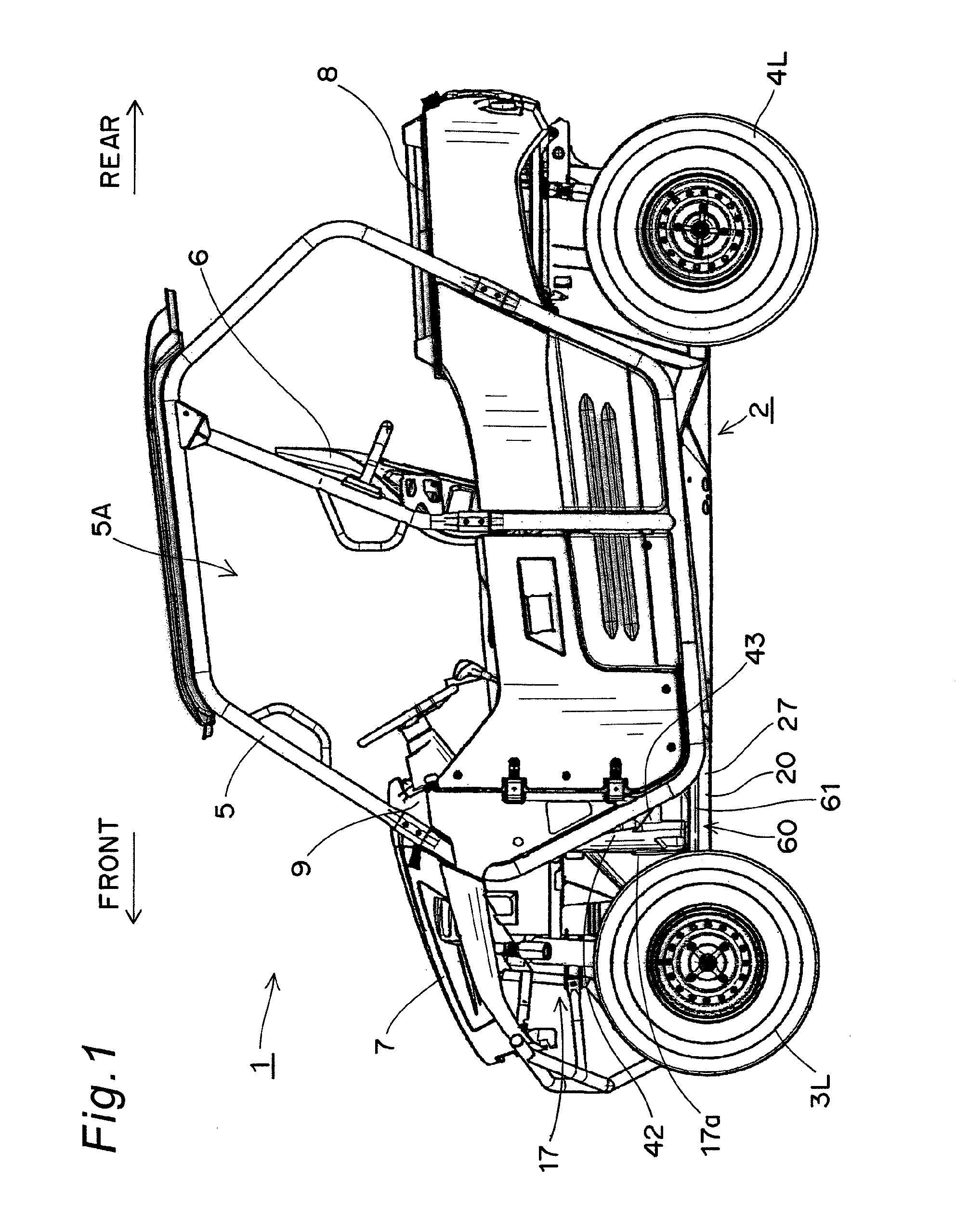
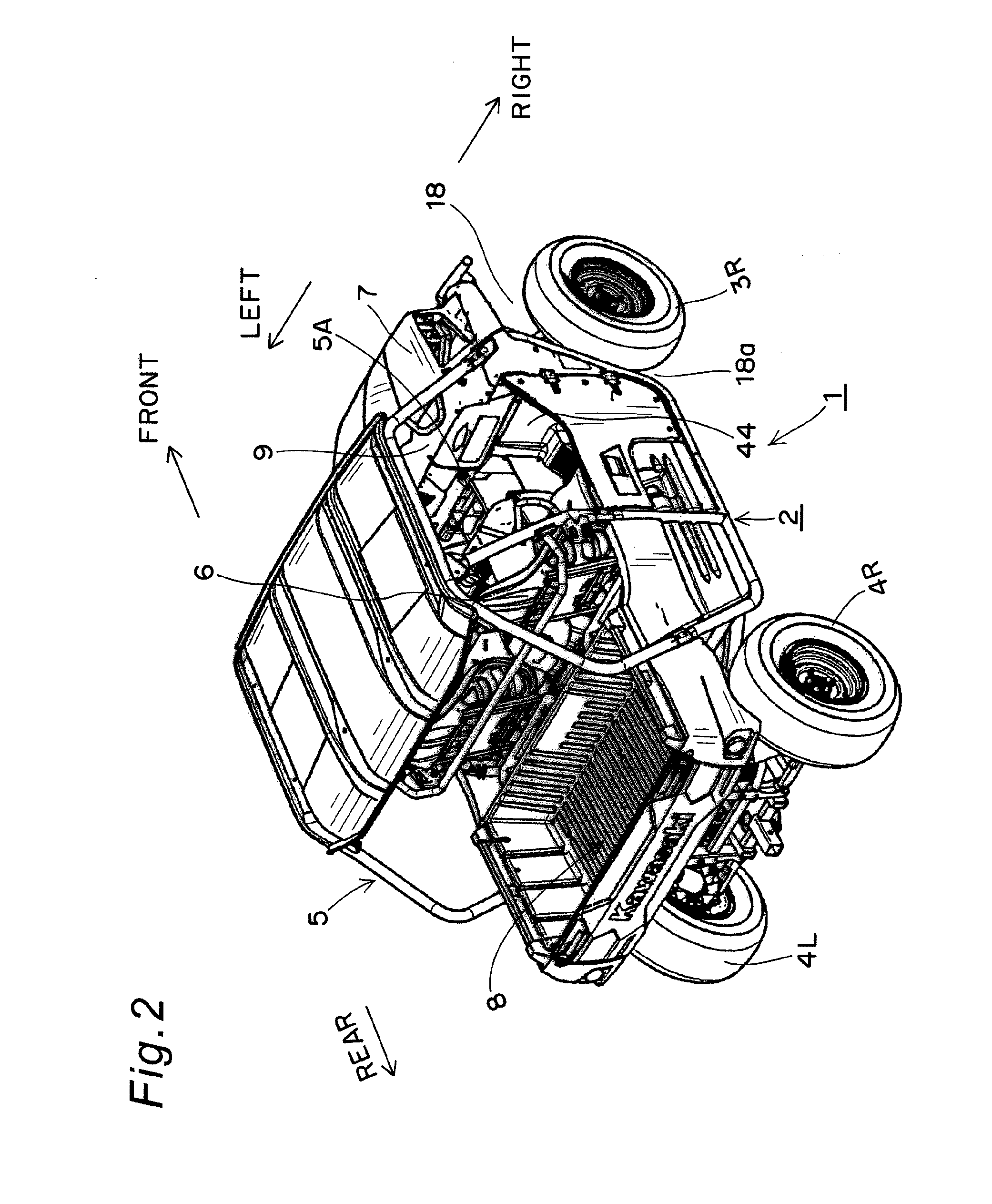
[0037]FIG. 1 is a left side view showing a utility vehicle 1 according to a first embodiment of the present invention. FIG. 2 is a perspective view of the utility vehicle 1 shown in FIG. 1, viewed downward from an oblique rear right direction. The utility vehicle 1 is used mainly for running in off-road circumstances like a grass field, a gravel field, and a sand field as well as an unpaved mountain path, an unpaved path through a wood, a mud path, and a rocky field.
[0038](Overall Structure of Utility Vehicle 1)
[0039]The utility vehicle 1 shown in FIGS. 1 and 2 is a four-wheel vehicle provided with a left front wheel 3L and a right front wheel 3R respectively located in the left and the right of the front part of a vehicle-body frame 2 and with a left rear wheel 4L and a right rear wheel 4R respectively located in the left and the right of the rear part of the vehicle-body frame 2. The utility vehicle 1 has a cabin 5A surrounded by a cabin frame, i.e., a ROPS (Roll-Over Protective S...
second embodiment
[0054]FIG. 7 is a left side view of a vehicle-body frame 2 of a utility vehicle 1 according to a second embodiment. FIG. 8 is an enlarged perspective view of a left front wheel 3L and its periphery shown in FIG. 7, viewed upward from an oblique front left direction. Here, in the present embodiment, like parts to the first embodiment described above are designated by like numerals and hence their description is omitted.
[0055]As shown in FIG. 7, a left wheel house 17 is formed so as to surround the left front wheel 3L. Then, a left mud guard wall 43 for separating the cabin 5A from a space 17a on the rear side of the left front wheel 3L in the left wheel house 17 is attached to a left front cross member 27.
[0056](Structure of Left Front Under Guard 80)
[0057]As shown in FIG. 8, a left front under guard 80 is attached directly to at least the outer side surface of the lower part of the left mud guard wall 43. The left front under guard 80 has a shape that follows (corresponds to) the ou...
third embodiment
[0061]FIG. 9 is a perspective view of a vehicle-body frame 2 of a utility vehicle 1 according to a third embodiment of the present invention, viewed downward from an oblique front left direction. FIG. 10 is a perspective view of the vehicle-body frame 2 shown in FIG. 9, viewed downward from an upper right direction. Here, also in the present embodiment, like parts to the first and the second embodiments described above are designated by like numerals and hence their description is omitted.
[0062]As shown in FIGS. 9 and 10, similarly to the first embodiment, the left wheel house 17 and the right wheel house 18 are formed such as to respectively surround a left front wheel and a right front wheel (not shown). A left mud guard wall 43 and a right mud guard wall 44 for separating the cabin 5A from the spaces 17a and 18a on the rear sides of the left front wheel and the right front wheel in the left wheel house 17 and the right wheel house 18 are attached to the left front cross member 27...
PUM
 Abstract
Description
Claims
Application Information