Brace for dynamically correcting the bending of the joints of the lower limb

a dynamic correction and joint technology, applied in the field of mechanical braces, can solve the problems of affecting the function of the body, and affecting the ability of the body to bend the knee joint,

Inactive Publication Date: 2013-11-19
CERIOLI MARIO
View PDF14 Cites 5 Cited by
  • Summary
  • Abstract
  • Description
  • Claims
  • Application Information

AI Technical Summary

Benefits of technology

[0026]According to a further preferred embodiment of the invention, the dynamic brace also comprises a pelvis grip and at least one of said flat flexible profiles further connects said thigh grip to the pelvis grip. According to other embodiments, the flat flexible profiles can comprise a bundle of profiles or threadlike elements, with the same or different flexibility, and the fixing means to the thigh and leg grips are arranged for allowing a sliding of the profiles to adjust the length of the portions positioned above or below them.

Problems solved by technology

In subjects affected by cerebral pathologies of prenatal or perinatal origin, the tendency to adopt a bent position of the knee joint often develops, due to insecurity that derives from adoption of an aligned erect position.
This unnatural position tends to cause progressive lengthening of the extensor tendons, with shortening of the flexors, which over time causes a worsening of the condition of the subject, also with involvement of the other joints of the lower limb, i.e. the ankle and hip joints.
However, this embodiment does not allow correction of the bending of the ankle and hip joints, which must be usually implemented in children with motor development disorder.
Moreover, it does not allow freedom of movement and changes of position that are typical needs of the child, and therefore becomes intolerable to the wearer.
The defects of currently known devices consist essentially in that fact that:they are heavy and cumbersome devices;they limit the freedom of the person, reducing the possibility of movement;they limit the functional exercise of walking, with anti-therapeutic effect;they hamper passage from a sitting or lying position to an upright posture;they cause excessive heating of the limb during the summer season;they are generally not well tolerated, particularly by children.

Method used


Image

  • Brace for dynamically correcting the bending of the joints of the lower limb
  • Brace for dynamically correcting the bending of the joints of the lower limb
  • Brace for dynamically correcting the bending of the joints of the lower limb

Examples


Embodiment Construction

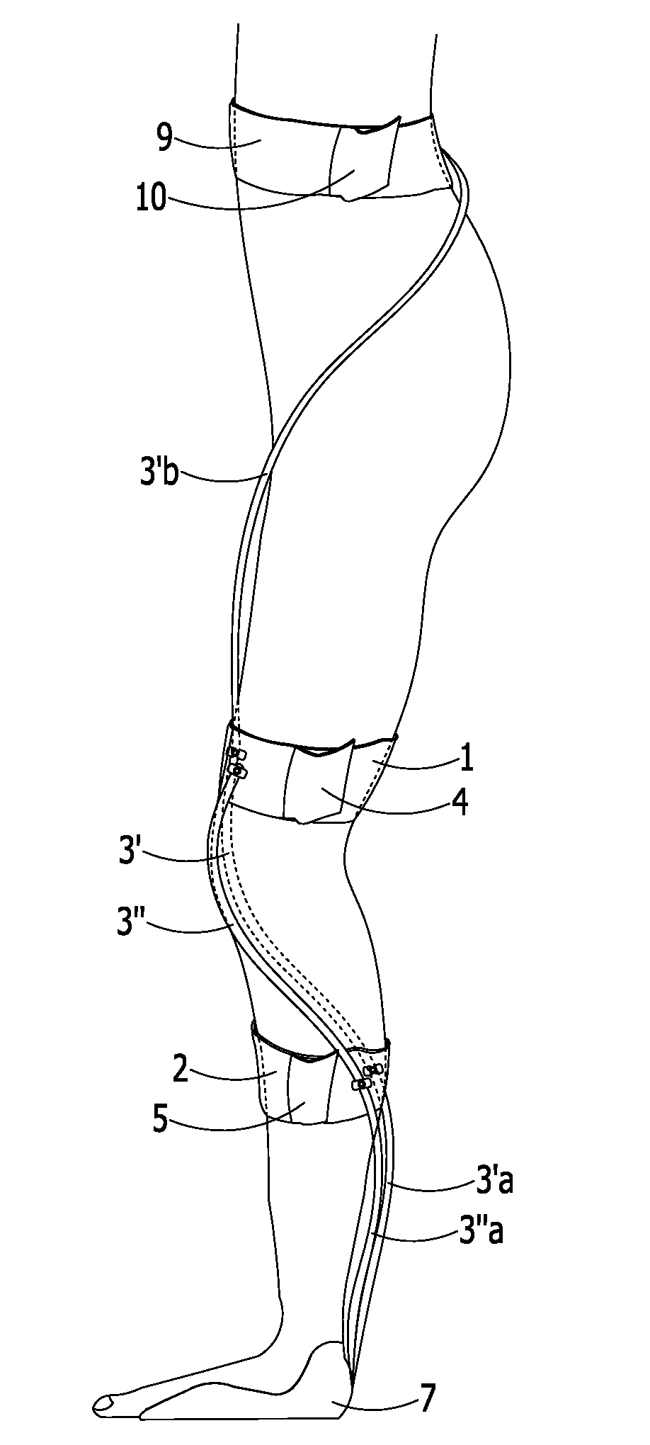
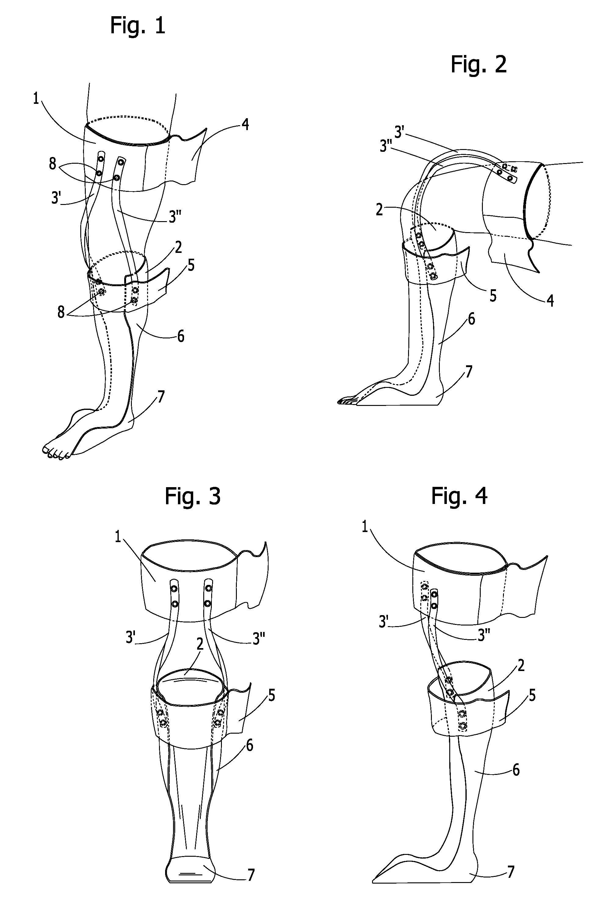
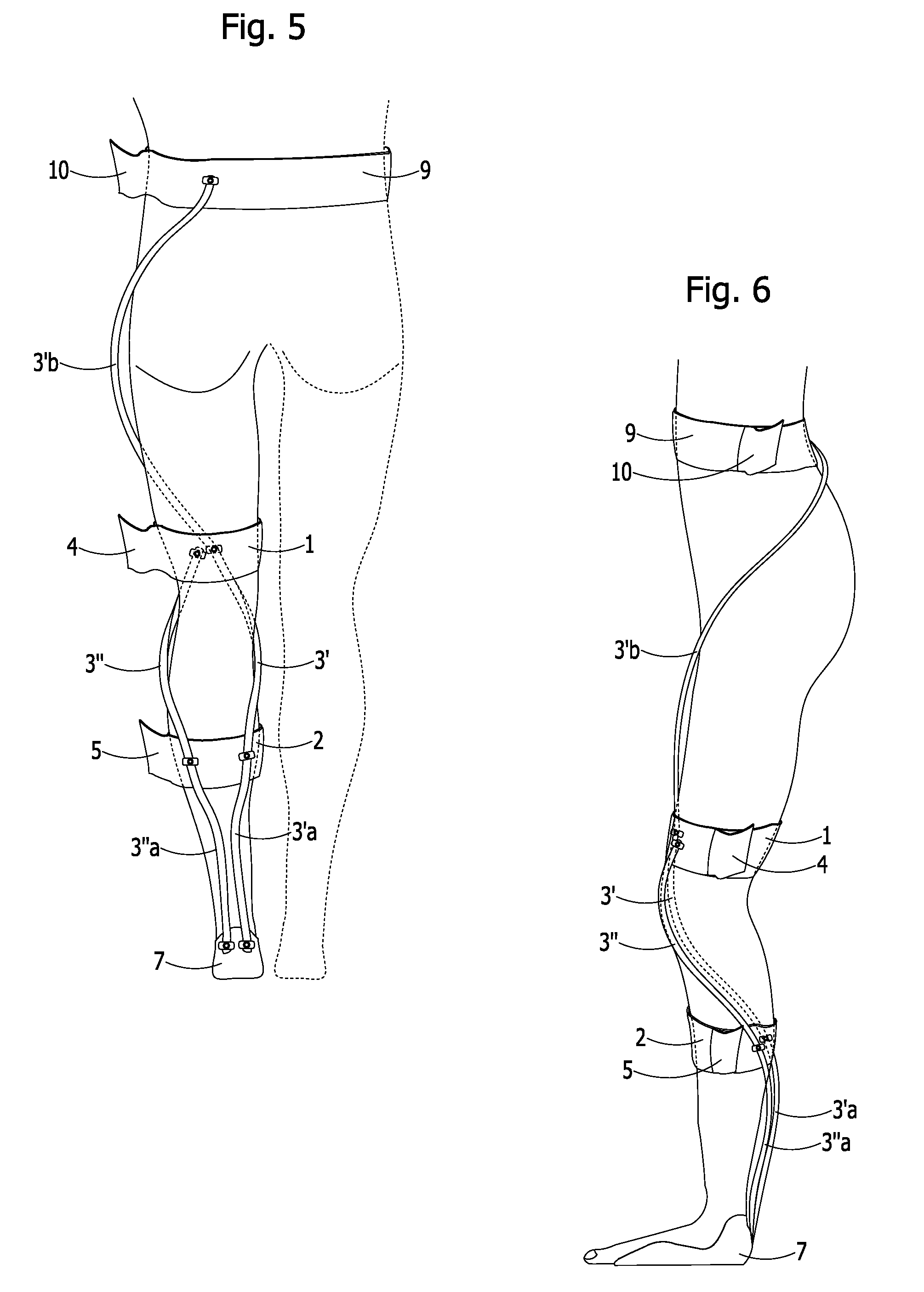
[0038]With reference to the figures, the brace comprises a thigh grip 1, a leg grip 2 and two flat flexible profiles 3′ and 3″ that connect, in a non-rigid elastic manner, the thigh grip 1 to the leg grip 2.

[0039]The thigh grip 1 comprises a band of inextensible material, such as polypropylene or other plastic, metal or composite material of known type, open on the side of the thigh, where reversible closing means are present, for example formed by a band 4 fixable to the thigh grip by Velcro®.

[0040]The leg grip 2 comprises a band of inextensible material analogous to that of the thigh grip, open in the anterior portion of the leg, where reversible closing means are present, analogous to those of the thigh grip, comprising a band 5.

[0041]With particular reference to FIGS. 1-4, the band forming the leg grip 2 extends posteriorly to the leg itself with a shaped element 6 made of flexible plastic material arranged for lying along the calf and a substantially rigid shaped element 7 arra...


PUM


Abstract

A brace for dynamically correcting the bending of the joints of the lower limb including a thigh grip (1), a leg grip (2), connection means between said thigh grip and said leg grip, wherein said connection means includes at least two flat flexible profiles (3′, 3″) that work in extension, elastically opposing the bending of the knee, and said brace comprises a foot grip (7) and further flexible means (6, 3′a, 3″a) arranged for connecting said leg grip (2) to said foot grip (7), which work in extension elastically opposing the bending of the ankle.

Description

BACKGROUND OF THE INVENTION[0001]The invention relates to a mechanical brace and in particular to an ankle, knee and hip orthesis, aimed at preventing and correcting deformation in bending of the joints, and at developing dynamic balance in children with motor development disorder.[0002]In subjects affected by cerebral pathologies of prenatal or perinatal origin, the tendency to adopt a bent position of the knee joint often develops, due to insecurity that derives from adoption of an aligned erect position. This unnatural position tends to cause progressive lengthening of the extensor tendons, with shortening of the flexors, which over time causes a worsening of the condition of the subject, also with involvement of the other joints of the lower limb, i.e. the ankle and hip joints.[0003]To attempt to prevent or correct deformation in the bending of the knee in the child or adult, devices are used, which are fitted to the limbs to correct the defect in posture and carriage.[0004]For ...

Claims


Application Information

Patent Timeline
Patent Type & Authority Patents(United States)
IPC IPC(8): A61F5/00
CPCA61F5/0111A61F5/0123A61F2005/0148A61F2005/0179
Inventor CERIOLI, MARIO
Owner CERIOLI MARIO
Why Eureka
Try Eureka