
Surgical disc removal tool

a technology for disc removal and surgical instruments, applied in the field of surgical devices, can solve the problems of being purely manual, unable to remove discs, and each conventional device suffers from one or more drawbacks, so as to improve the ability of surgeons to remove at leas

Active Publication Date: 2013-11-19
GLOBUS MEDICAL INC
View PDF4 Cites 69 Cited by
  • Summary
  • Abstract
  • Description
  • Claims
  • Application Information

AI Technical Summary

Benefits of technology

The device enhances surgical efficiency by reducing fatigue and capital costs, providing precise control and versatility in tissue removal, and eliminating the need for expensive airflow-based suction systems, while ensuring clear visualization of the collection process.

Problems solved by technology

Severe, even debilitating, pain can result from such damage.
However, each conventional device suffers from one or more drawbacks.
Conventional devices exist which suffer from the problem of being purely manual.
Additionally, such manual devices require significantly more time to complete the procedure as opposed to devices which have one or more powered, or otherwise mechanical, components.
However, merely providing for a powered device that facilitates removal of tissue associated with a spinal disc does not completely remedy the drawbacks of conventional devices.
Many existing powered disc removal devices require expensive capital equipment to power the device.
Additionally, surgeons are reluctant to use powered devices designed for removal of at least a portion of tissue associated with a spinal disc because the devices are overpowered or lack proper safety measures.
Furthermore, conventional devices have drawbacks in their ability to remove tissue associated with the spinal disc that has been severed.
Such an approach includes various drawbacks, including requiring a device capable of generating the suction.
This requires at least the extra capital expense of purchasing a device capable of generating the requisite suction.

Method used


Image

  • Surgical disc removal tool
  • Surgical disc removal tool
  • Surgical disc removal tool

Examples


Embodiment Construction

[0036]The aspects of the present disclosure and the various features and advantageous details thereof are explained more fully with reference to the non-limiting aspects and examples that are described and / or illustrated in the accompanying drawings and detailed in the following description. It should be noted that the features illustrated in the drawings are not necessarily drawn to scale, and features of one aspect may be employed with other aspects as the skilled artisan would recognize, even if not explicitly stated herein. Descriptions of well-known components and processing techniques may be omitted so as to not unnecessarily obscure the aspects of the present disclosure. The examples used herein are intended merely to facilitate an understanding of ways in which the present disclosure may be practiced and to further enable those of skill in the art to practice the aspects of the present disclosure. Accordingly, the examples and aspects herein should not be construed as limiti...


PUM


Abstract

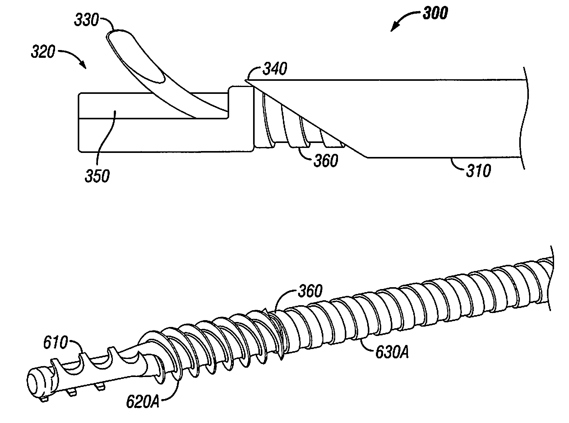
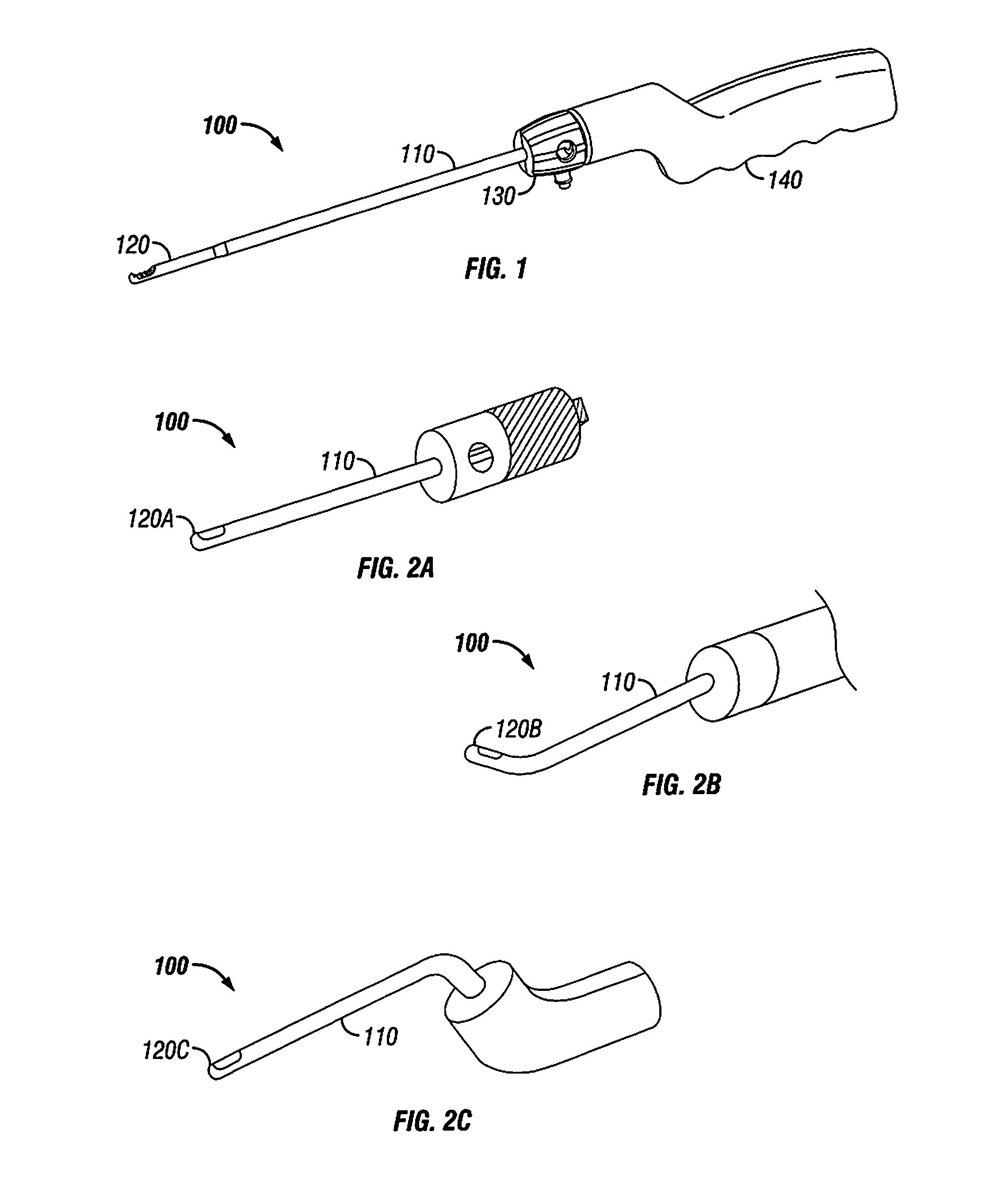
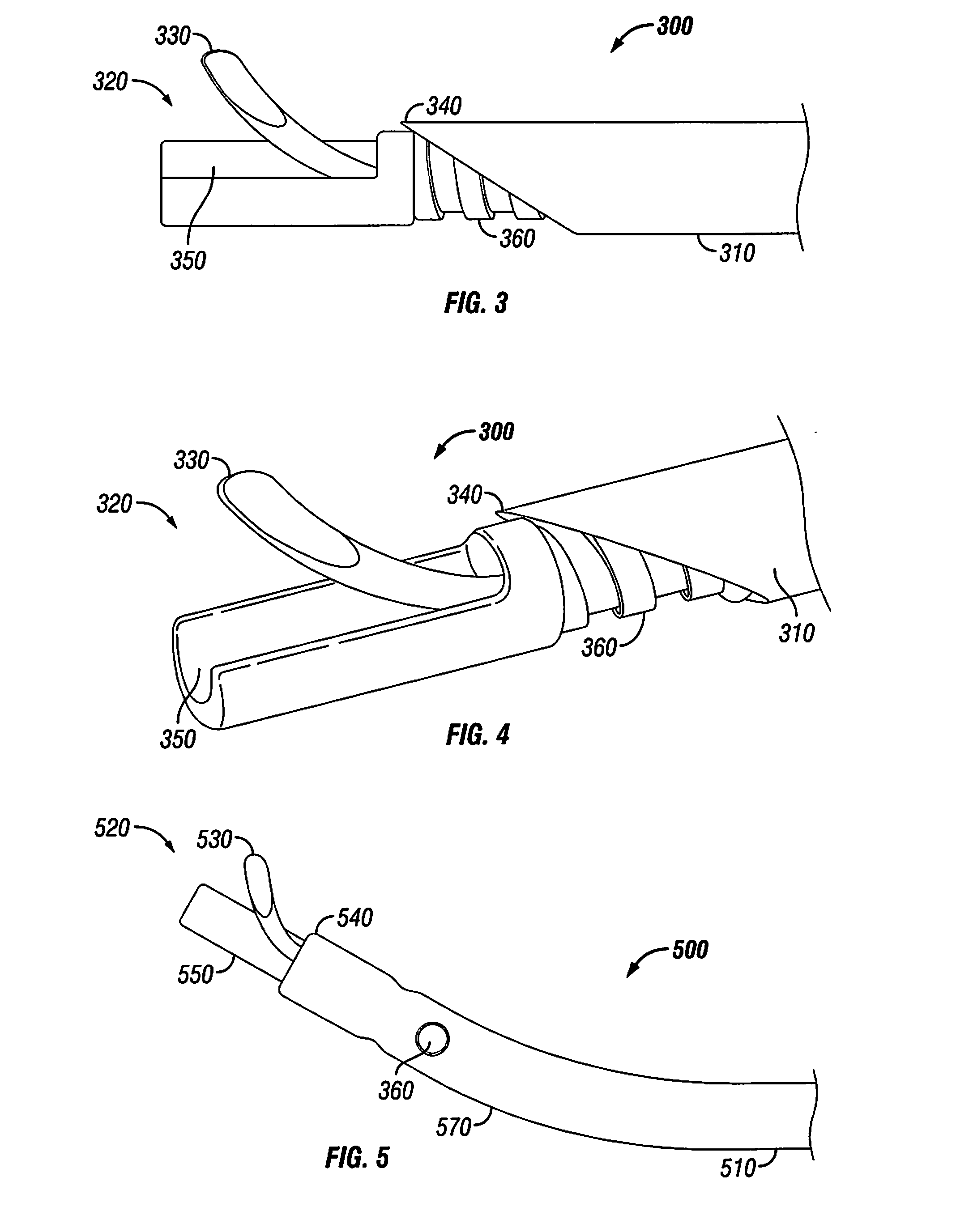
The disclosure provides a tissue removal device including customizable tips. The tissue removal device may include an outer shaft and a threaded shaft. One aspect of disclosure may include a shaft cutting tool that emerges from the end of the outer shaft. Another aspect of the disclosure may include a flexible cutting blade extending from the threaded shaft. Threaded shaft may be driven by a driving mechanism in order to provide an auger-like suction mechanism to facilitate the transfer of removed tissue to a collection chamber that is coupled to the outer shaft and the threaded shaft.

Description

BACKGROUND OF THE PRESENT DISCLOSURE[0001]1. Field of the Present Disclosure[0002]The present disclosure is generally directed to a surgical device. More specifically, the disclosure may be directed to a surgical device that facilitates the removal of tissue.[0003]2. Related Art[0004]A spine comprises a series of small bones referred to as vertebrae. Spinal discs are fixed in place between each pair of vertebrae and function like a pad or cushion to prevent the vertebrae from grinding against each other and permit the spine to be flexible. A variety of scenarios may exist where damage to one or more of these spinal discs may occur including, but not limited to, injury and illness. Severe, even debilitating, pain can result from such damage.[0005]Surgical procedures exist that attempt to alleviate the pain that accompanies such damage. At least one of these procedures may involve the removal of at least a portion of tissue associated with a spinal disc. Many conventional devices curr...

Claims


Application Information

Patent Timeline
Patent Type & Authority Patents(United States)
IPC IPC(8): A61B17/32
CPCA61B17/32002A61B17/320725A61B17/22A61B17/320016A61B17/320783A61B2017/00261A61B2017/320733A61B2017/00685A61B17/320708A61B17/320758A61B2017/320064
Inventor YOON, SAMUELAGARD, RYANPALMER, RORYPASTOR, JASONSUH, SEAN
Owner GLOBUS MEDICAL INC
Learn More