Electronic equipment, control information transmission and reception methods having bidirectional communication using predetermined lines

a technology of control information and transmission methods, applied in the direction of instruments, television systems, signal generators with optical-mechanical scanning, etc., can solve the problems of unsuitable control speed and data structur

Active Publication Date: 2013-11-19
SONY CORP
View PDF44 Cites 8 Cited by
  • Summary
  • Abstract
  • Description
  • Claims
  • Application Information

AI Technical Summary

Benefits of technology

[0025]According to the invention, a communication unit that performs bidirectional communication using predetermined lines included in a transmission line is included. The communication unit is used to transmit control information to another electronic equipment. The operating state of the another electronic equipment can be quickly controlled. According to the invention, a communication unit that performs bidirectional communication using predetermined lines included in a transmission line is included. The communication unit is used to receive control information from another electronic equipment. An operating state is controlled based on the control information. The operating state can be quickly controlled from the another electronic equipment side.

Problems solved by technology

The transmission speed and data structure are therefore unsuitable for control that requires a high-speed response or transmission of control information whose length exceeds 16 bytes.

Method used


Image

  • Electronic equipment, control information transmission and reception methods having bidirectional communication using predetermined lines
  • Electronic equipment, control information transmission and reception methods having bidirectional communication using predetermined lines
  • Electronic equipment, control information transmission and reception methods having bidirectional communication using predetermined lines

Examples


Embodiment Construction

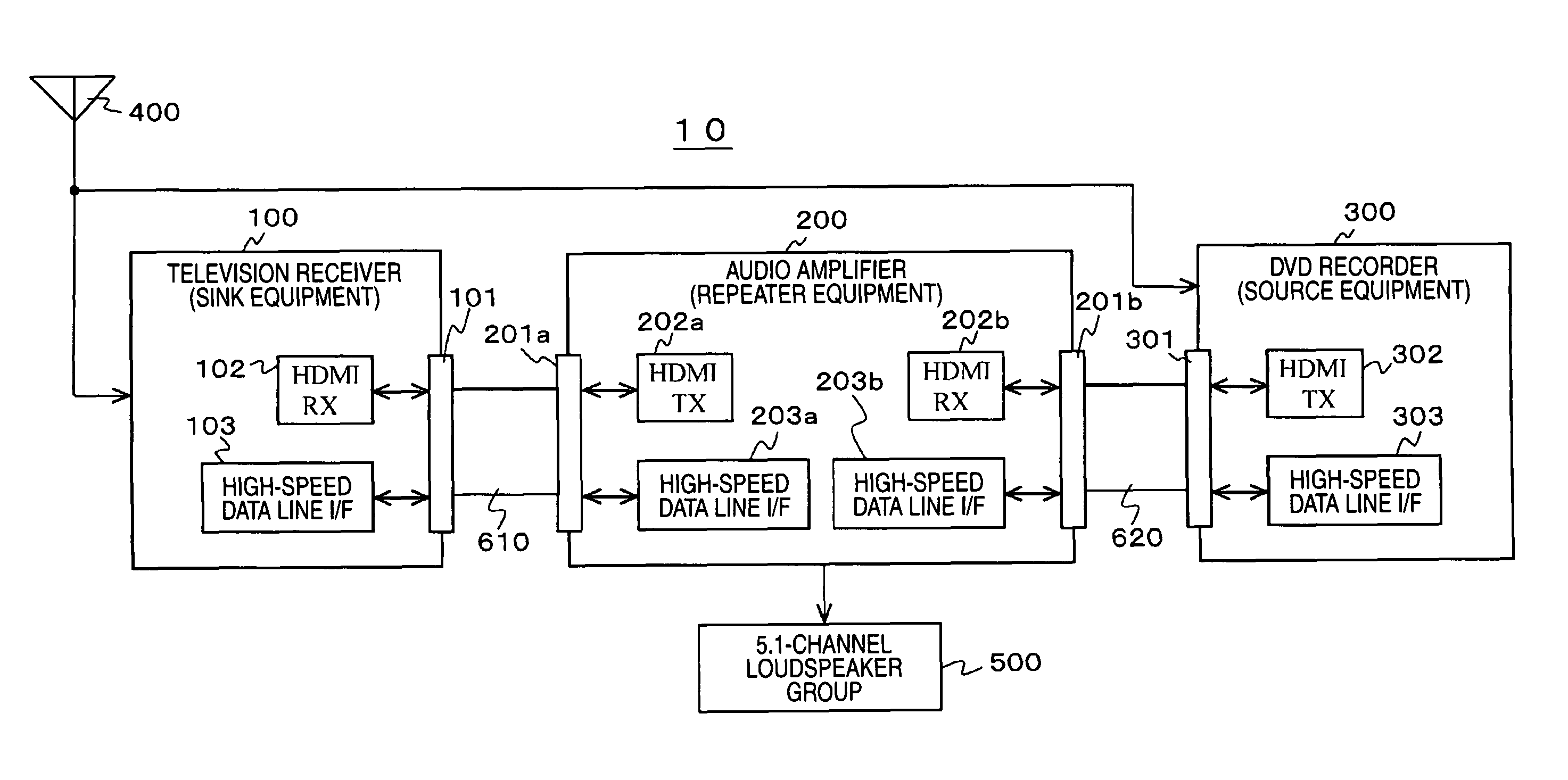
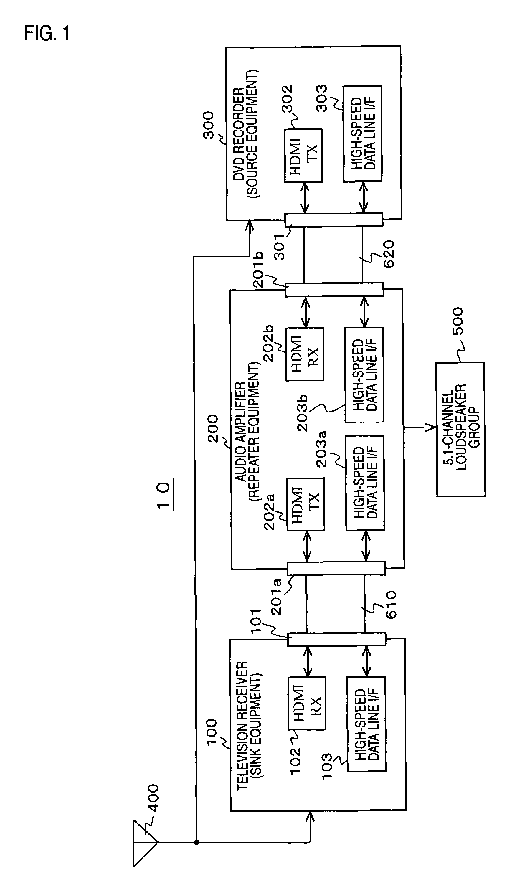
[0042]Referring to the drawings, an embodiment of the invention will be described below. FIG. 1 shows an example of the configuration of a communication system 10 as an embodiment. The communication system 10 includes a television receiver 100 serving as sink equipment, an audio amplifier 200 serving as repeater equipment, and a DVD recorder 300 serving as source equipment. To the television receiver 100 and DVD recorder 300, a television broadcast receiving antenna 400 is connected. To the audio amplifier 200, a 5.1-channel loudspeaker group 500 is connected.

[0043]The television receiver 100 and audio amplifier 200 are interconnected over an HDMI cable 610. The television receiver 100 is provided with an HDMI terminal 101 to which an HDMI receiving unit (HDMIRX) 102 and a high-speed data line interface (I / F) 103 included in a communication unit are connected. The audio amplifier 200 is provided with an HDMI terminal 201a to which an HDMI transmitting unit (HDMITX) 202a and a high-s...


PUM


Abstract

Electronic equipment and methods for permitting quick control of the operating state of a source equipment side from sink equipment. A television receiver (sink equipment) 100 and an amplifier (repeater equipment) 200 are interconnected over an HDMI cable 610, and the amplifier 200 and a DVD recorder (source equipment) 300 are interconnected over an HDMI cable 620. Each of the pieces of equipment includes, in addition to an HDMI receiving unit and an HDMI transmitting unit, a high-speed data line I / F included in a bidirectional communication unit that uses predetermined lines of the HDMI cable. The bidirectional communication unit is used to transmit channel selection information, a remote control code instructing recording, “theater mode” designating information, a remote control code, or the like from the television receiver 100 to the audio amplifier 200 or DVD recorder 300.

Description

CROSS-REFERENCES TO RELATED APPLICATIONS[0001]The present application is a national phase entry under 35 U.S.C. §371 of International Application No. PCT / JP2007 / 071649 filed Nov. 7, 2007, published on May 15, 2008 as WO 2008 / 056707 A1, which claims priority from Japanese Patent Application No. JP 2006-301486 filed in the Japanese Patent Office on Nov. 7, 2006, Japanese Patent Application No. JP 2007-050426 filed in the Japanese Patent Office on Feb. 28, 2007, and Japanese Patent Application No. JP 2007-201517 filed in the Japanese Patent Office on Aug. 2, 2007.TECHNICAL FIELD[0002]The present invention relates to electronic equipment, a control information transmission method, and a control information reception method that employ a communication interface, for example, the high definition multimedia interface (HDMI). More particularly, the invention is concerned with electronic equipment that includes a communication unit which performs bidirectional communication using predetermin...

Claims


Application Information

Patent Timeline
Patent Type & Authority Patents(United States)
IPC IPC(8): H04N11/00H04N5/60H04N7/26H04N5/44H04N7/16
CPCH04B1/205H04N5/4403H04N5/775H04N7/163H04N5/44H04N21/42646H04N21/43615H04N21/43632H04N5/38H04N21/4135H04N21/42204H04N21/426G09G5/006G09G2370/047G09G2370/06G09G2370/12H04N5/602H04N7/015H04N21/4334H04N21/43635
Inventor NAKAJIMA, YASUHISAKIKUCHI, HIDEKAZUMITSUHASHI, TAKAMICHI
Owner SONY CORP
Why Eureka
Try Eureka