Utility load control management communications protocol

Inactive Publication Date: 2008-06-05
CANNON TECH
View PDF20 Cites 59 Cited by
  • Summary
  • Abstract
  • Description
  • Claims
  • Application Information

AI Technical Summary

Benefits of technology

[0015]The invention facilitates communication between a utility and a thermostat to manage demand of thermostat-controlled devices. A utility can therefore reduce peak demand by pre-cooling a thermostat-controlled space before a peak demand period, for example in an early summer afternoon. The utility can remotely turn off air conditioners during the peak time, thereby shedding some load during peak demand time while the resident remains reasonably comfortable during the same period. Additional appliances such as hot water heaters or area lighting are similarly controlled to reduce power consumption during peak load periods with minimal disruption to residential or business customers. Industrial and office customers will also have machines and appliances that are controlled via wireless communication from the utility to reduce peak load demand. The invention thereby provides a way to quickly control many such appliances and machines.
[0016]The invention also provides a computer-implemented communications protocol to address a large set of customers, a set of specific appliances, selected geographic regions, or selected groups of appliances for a single or group of customers as desired in various embodiments. The invention thereby provides a load shedding protocol that is able to operatively address not only one specific custom

Problems solved by technology

It is well understood in the industry that the base demand is the least expensive energy to generate, while the peak demand can be the most expensive, requiring expensive peaking generators or the purchase of additional power from other utilities on a spot market.
If the peak demand exceeds the capacity of the utility to generate or purchase electricity, the quality of the power provided can decline, resulting in brown-outs or load-shedding with involuntary black-outs to at least some of the utility's customers.
Poor quality of delivered power can cause damage to expensive equipment of both the customer and the utility.
Additional generating capacity is difficult and expensive to obtain, sometimes requiring the building of additional power plants.
Regulatory delays and increased public opposition to the pollut

Method used


Image

  • Utility load control management communications protocol
  • Utility load control management communications protocol
  • Utility load control management communications protocol

Examples


Example

[0041]While the invention is amenable to various modifications and alternative forms, specifics thereof have been shown by way of example in the drawings and will be described in detail herein. It should be understood, however, that the intention is not to limit the invention to the particular embodiments described. On the contrary, the intention is to cover all modifications, equivalents, and alternatives falling within the spirit and scope of the invention as defined by the appended claims.

DETAILED DESCRIPTION OF THE INVENTION

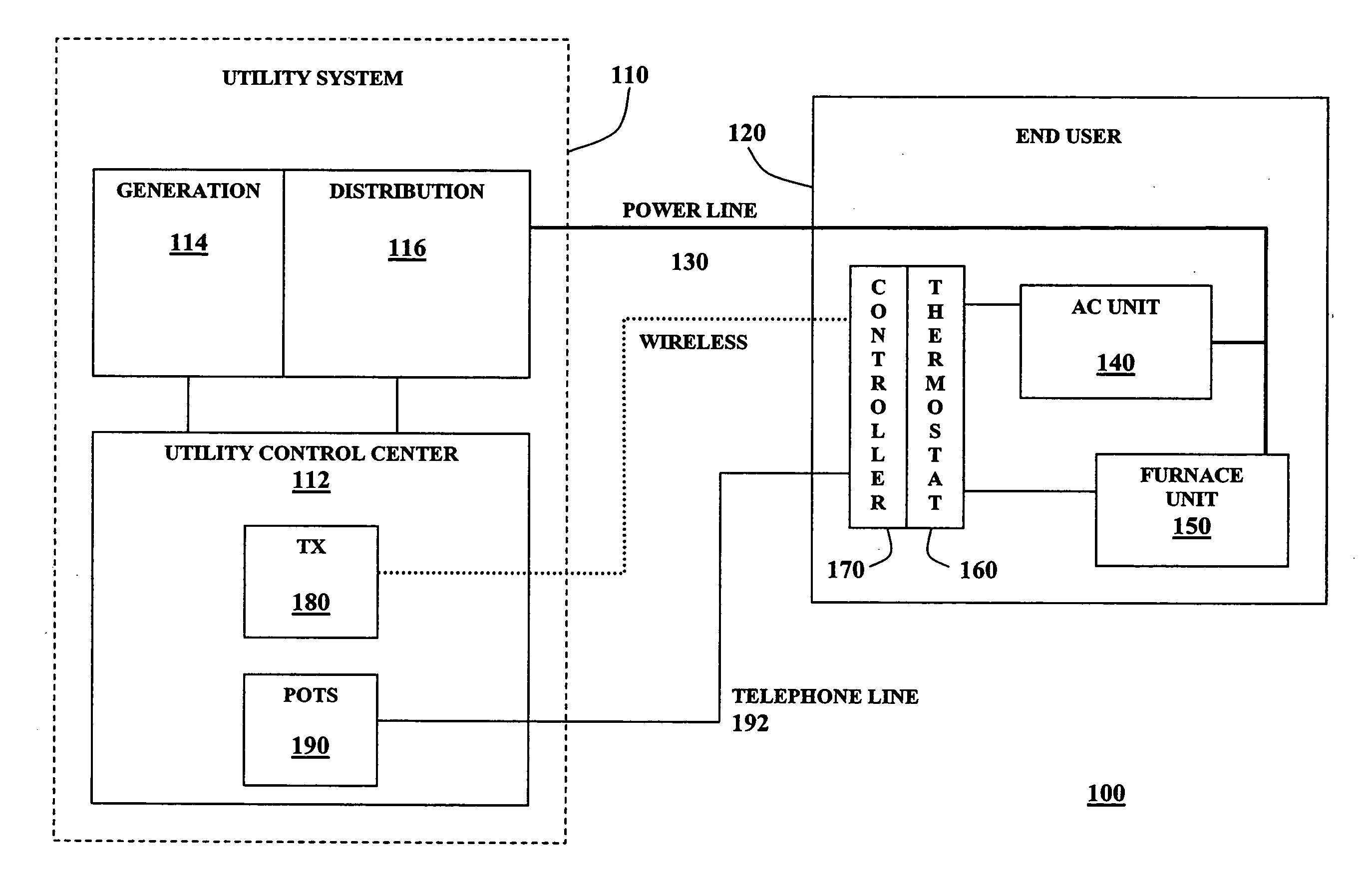
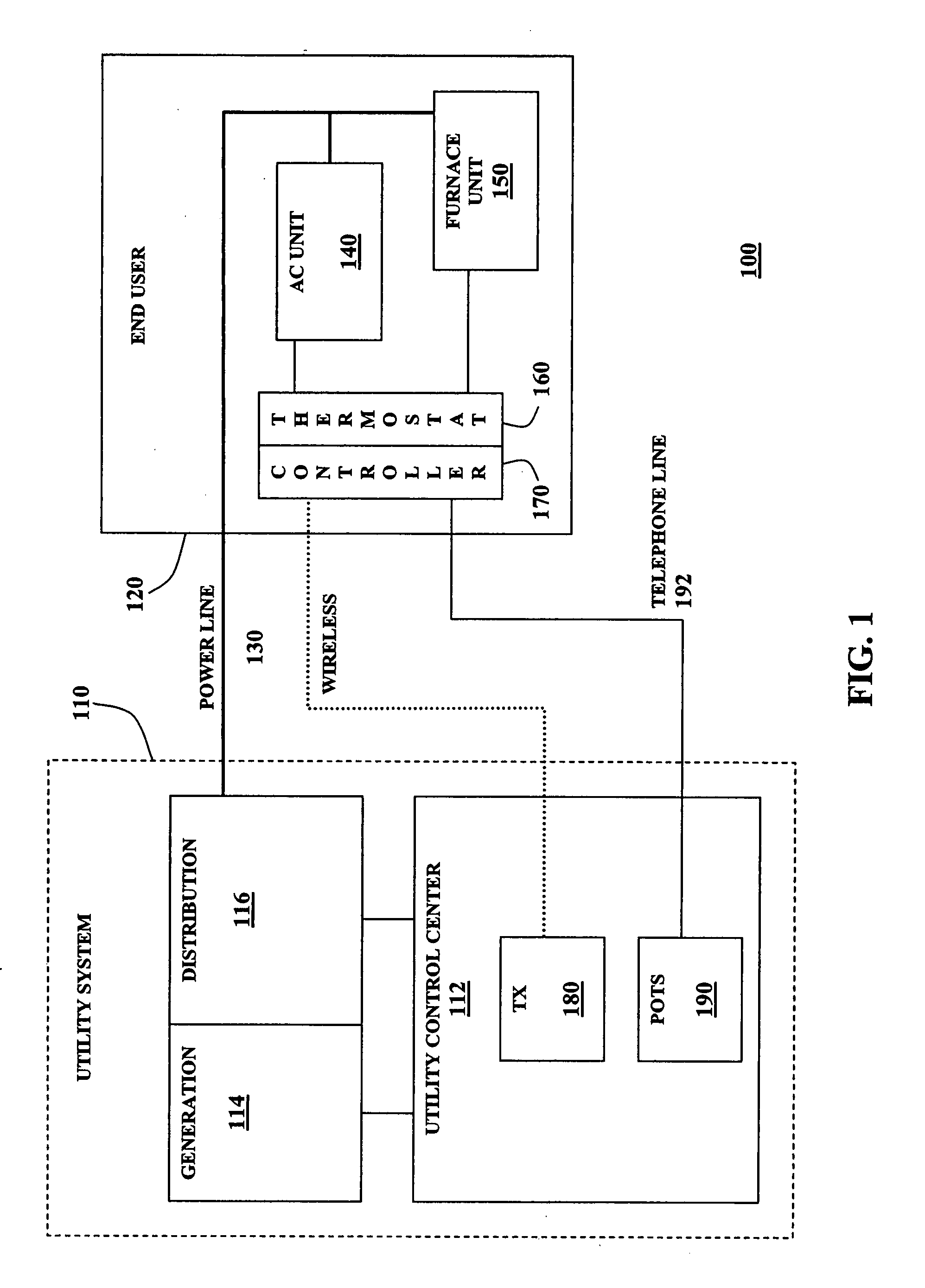
[0042]Various embodiments of the protocol, system, and method of the invention provide control and management of a utility power-consuming load via a communications protocol administered by a master utility station. The invention can be more readily understood by reference to FIGS. 1-20, the Appendix, and the following description. The Appendix includes exemplary protocol message formats in accordance with various embodiments of the invention and is incorpora...


PUM


Abstract

A load control management protocol, system, and method that address many different customers, individually, in geographic groups, or in other predefined groups to control at least one or more electrical power consuming appliances are disclosed. The computer-implemented protocol provides wired and wireless communication schemes that enable a utility to quickly and efficiently communicate commands and messages to end user devices. Specific electrically powered appliances and certain uses of electricity can therefore be managed by communicating with the controllers of those appliances, providing management of a utility load during peak price and consumption periods to prevent delivery interruptions.

Description

PRIOR APPLICATION[0001]This application is a divisional application of U.S. application Ser. No. 10 / 922,120 (Attorney docket No. 3034.09US02) filed Aug. 19, 2004, entitled “Utility Load Control Management Communications Protocol”, and claims priority to U.S. Application Ser. No. 60 / 496,532, (Attorney Docket No. 3034.09US01) filed Aug. 20, 2003, entitled “Utility Load Control Management Communications Protocol”, both of which are herein incorporated by reference.RELATED APPLICATION[0002]The present application claims the benefit of U.S. Provisional Application No. 60 / 496,532 filed Aug. 20, 2003, which is incorporated herein in its entirety by reference.FIELD OF THE INVENTION[0003]The invention generally relates to utility load control, and more particularly to managing utility load by communicating control commands to remotely located utility equipment.BACKGROUND OF THE INVENTION[0004]Utility companies, specifically electricity generating and distributing utilities, must be able to g...

Claims


Application Information

Patent Timeline
IPC IPC(8): G06F17/00
CPCH04L12/10H04L12/2818H04L2012/2841H04L67/125H04L2012/2845H04L2012/285H04L2012/2843Y04S40/18
Inventor CANNON, JOELCOX, ROBERTROGNLI, ROGER
Owner CANNON TECH
Why Eureka
Try Eureka