Switch control with light beams

Active Publication Date: 2005-12-13
NORTHROP GRUMMAN SYST CORP
View PDF17 Cites 0 Cited by
  • Summary
  • Abstract
  • Description
  • Claims
  • Application Information

AI Technical Summary

Benefits of technology

[0004]By using the foregoing techniques, switches may be controlled with hardware which is smaller and lighter than the known hardware. In addition, thousands of switches may be activated and controlled quickly without any wiring system.

Problems solved by technology

For example, in applications involving thousands of MEMs, the large number of requisite control lines quickly overwhelm the available area on the chip, thereby limiting performance.

Method used


Image

  • Switch control with light beams
  • Switch control with light beams
  • Switch control with light beams

Examples


Embodiment Construction

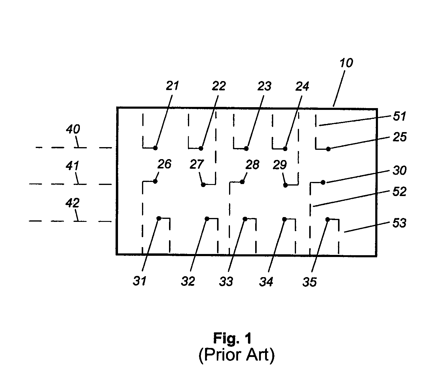
[0008]Referring to FIG. 1, a conventional MEMs circuit comprises a circuit board 10 on which 15 MEMs 21–35 (represented by dots) are mounted in a well known manner. MEMs 21–25 are arranged in a row along a line 40, MEMs 26–30 are arranged in a row along a line 41, and MEMs 31–35 are arranged in a row along a line 42. The MEMs 21–35 are spaced 1 unit from each other and are accessed and controlled by independent conductors grown into circuit board 10, such as control lines 51, 52 and 53. Circuit board 10 may comprise a semiconductor chip, or a conventional circuit board on which copper control lines are etched. Additional details about MEMs and lines used to control them are described in U.S. application Ser. No. 09 / 676,007, entitled “Radio Receiver Automatic Frequency Control Techniques,” filed Sep. 29, 2000, in the name of Michael H. Myers, assigned to a common assignee and incorporated into this application by reference.

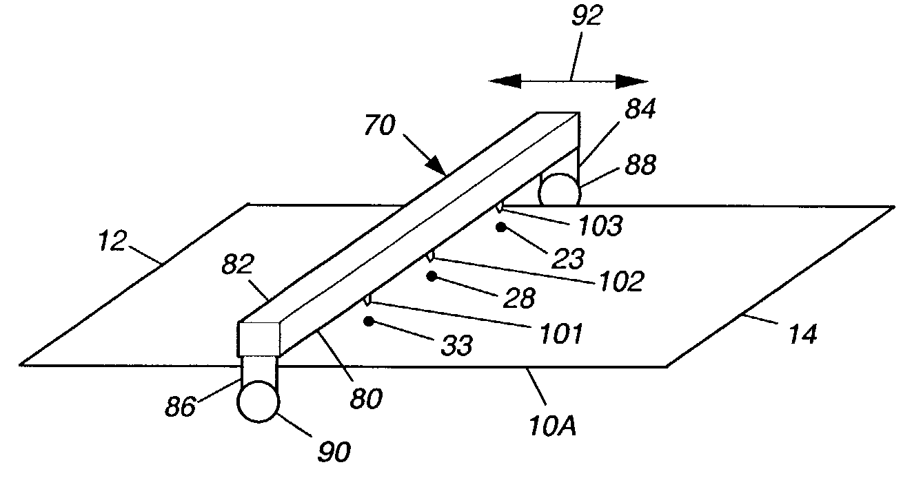
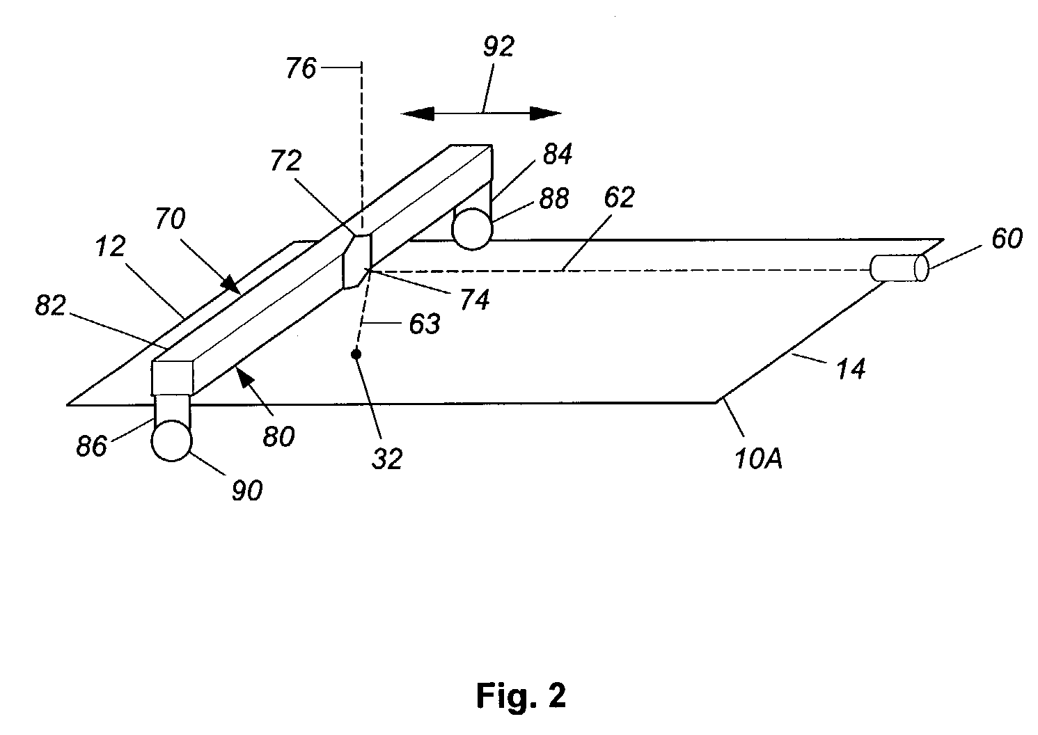
[0009]One application for circuit board 10 is a micro-thruste...


PUM


Abstract

An array of micro electromechanical switches (MEMs) (21–35) is actuated by a source of one or more light beams, such as a laser (60). A positioning unit (70) is arranged to direct the one or more light beams onto the MEMs, thereby actuating them without the need for control lines. The positioning unit may include a scanning unit (80) which positions a rotatable mirror (72).

Description

BACKGROUND OF THE INVENTION[0001]The present invention relates generally to control of switches, and more specifically, relates to control of switches with light beams.[0002]Micro electromechanical switches (MEMs) are finding applications in a variety of fields. The MEMs typically are controlled by control lines etched onto semiconductor chips. For many applications, the control lines occupy a significant percentage of the available chip real estate. For example, in applications involving thousands of MEMs, the large number of requisite control lines quickly overwhelm the available area on the chip, thereby limiting performance. This invention addresses the problem and provides a solution.BRIEF SUMMARY OF THE INVENTION[0003]The preferred embodiment is useful in an array of micro electromechanical switches. In such an environment, the preferred embodiment comprises generating one or more light beams. The one or more light beams are directed onto predetermined ones of the switches, pr...

Claims


Application Information

Patent Timeline
IPC IPC(8): H01H1/00H01H61/00H01H61/013
CPCH01H1/0036H01H61/00H01H61/013
Inventor HUANG, MARSHALL Y.
Owner NORTHROP GRUMMAN SYST CORP
Why Eureka
Try Eureka