
Actuator servo-control monitoring method and device

Active Publication Date: 2008-10-02
THALES SA
View PDF4 Cites 0 Cited by
  • Summary
  • Abstract
  • Description
  • Claims
  • Application Information

AI Technical Summary

Benefits of technology

[0031]robustness: the detection of the errors is fairly insensitive to the accidental triggering situations like those encountered, for example, in a situation where the speed of the actuator drops because of a significant mechanical load induced by a low hydraulic pressure level or a low level of the electrical power supply to the actuator.
[0032]selectivity: differentiating the type of the failure can make it possible to avoid a total disabling of the automatic pilot system when a failure of the second type occurs affecting a single hydraulic circuit.
[0033]responsiveness: the different value sensitivity thresholds are applied according to the nature of the error detected. The speed with which a failure of the first type is detected is adapted so that the pilot can retake control of the helicopter quickly.

Problems solved by technology

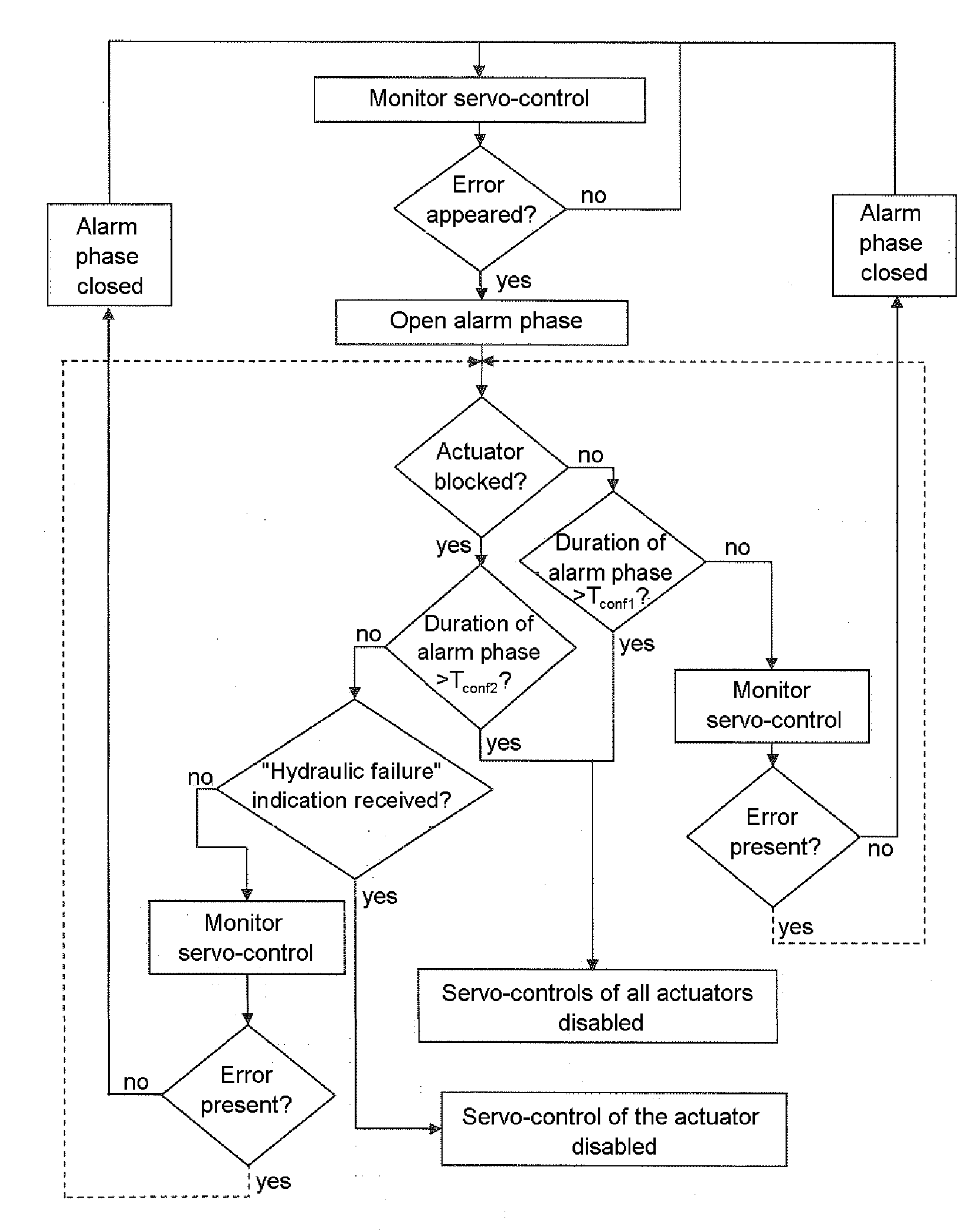
The analysis also establishes that a failure of the second type is induced exclusively by a failure affecting the hydraulic circuit associated with the actuator and that this failure produces a blockage of the actuator.

Method used


Image

  • Actuator servo-control monitoring method and device
  • Actuator servo-control monitoring method and device
  • Actuator servo-control monitoring method and device

Examples


Embodiment Construction

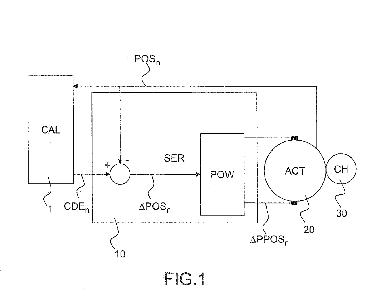
[0053]FIG. 1 represents a position servo-control loop of an actuator acting on a flight control of an aircraft, the flight control being assisted power-wise by a hydraulic circuit. The flight control is not shown in the figure.

[0054]The servo-control loop is part of an automatic pilot system, and comprises:[0055]a computation unit CAL, 1;[0056]at least one servo-control and power circuit SER, 10,[0057]at least one actuator ACT, 20.

[0058]The actuator is, for example, a series actuator, the body of which is fixed. A displacement of the output shaft of the actuator is mechanically transmitted to the hydraulic circuit which transmits it in turn to a flight control.

[0059]The hydraulic circuit CH, 30 which is associated with the actuator, is not part of the automatic pilot system.

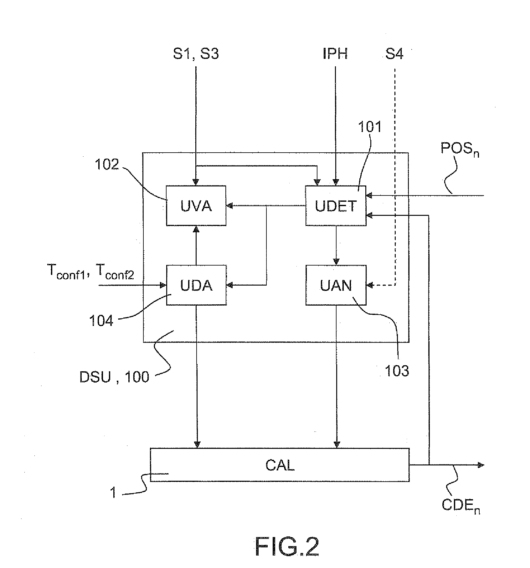
[0060]The computation unit CAL and the servo-control and power unit SER receive the position indication POS from the actuator ACT. The computation unit CAL generates a position set-point CDEn to be set at the end...


PUM


Abstract

An actuator displacement servo-control for aircraft flight controls is assisted by a hydraulic circuit, configured to deliver a hydraulic failure indication. The servo-control is generated from an actuator position indication and a position set-point indication computed by a computation unit. An alarm phase is opened on detection of a servo-control operating error and is kept open as long as the error is present. During the alarm phase it is determined whether the actuator is in blocked or divergent states. If blocked, it is determined whether the duration of the alarm phase exceeds a value Tconf2; If divergent, it is determined whether the duration of the alarm phase exceeds a value Tconf1. When blocked and the duration of the alarm phase does not exceed Tconf2, it is determined whether the hydraulic circuit indicates a hydraulic failure.

Description

RELATED APPLICATIONS[0001]The present application is based on, and claims priority from, France Application Number 0607757, filed Sep. 5, 2006, the disclosure of which is hereby incorporated by reference herein in its entirety.TECHNICAL FIELD[0002]The field of the invention is that of actuator servo-control monitoring methods and devices. The actuators concerned act, for example, on aircraft flight controls: such actuators are used, in particular, in helicopters.BACKGROUND OF THE INVENTION[0003]To stabilize and direct his craft, a helicopter pilot manually actuates piloting means (control stick, attitude control system and pedals) to act on the piloting axes of the helicopter (main rotor or tail rotor). A lateral or longitudinal displacement of the control stick can be used to respectively adjust the lateral or longitudinal axis of the helicopter by modifying the incidence of the blades of the main rotor. The attitude control system can be used to adapt the engine power to the fligh...

Claims


Application Information

Patent Timeline
IPC IPC(8): F15B18/00
CPCG05B23/0235
Inventor LE BASTARD, JEAN-CLAUDE
Owner THALES SA
Learn More