Method and system for automatically setting, adjusting, and monitoring load-based limits on a well service rig

a technology for servicing wells and load limits, applied in the field of automatic setting, adjusting, monitoring load-based limits on well service rigs, can solve the problems of increasing total hookload, rig damage, and workers around the well being injured, so as to prevent damage to the service rig and improve the effect of injury to workers around the well head

Active Publication Date: 2013-11-19
KEY ENERGY SERVICES
View PDF2 Cites 0 Cited by
  • Summary
  • Abstract
  • Description
  • Claims
  • Application Information

AI Technical Summary

Benefits of technology

[0007]The present invention is directed to controlling the operation of a well service rig based on rig load data. By removing the need for or limiting the capabilities of the operator during situations of increased load on the well service rig the ability to prevent damage to the service rig and injury to the workers around the well head can be improved.
[0008]For one aspect of the present invention, a method for controlling hookload on a well service rig can start by accepting a first hookload limit. The service rig can conduct one of many cycles for an activity at a well and can accept hookload data and the first cycle is being conducted. Each hookload data value that is accepted can be compared to the first hookload limit and, if the value is greater than the first hookload limit, can stop the first cycle of the activity from being completed. A first average hookload can be determined and a computer system can calculate a second hookload limit based on the first average hookload and an overpull value. The service rig can conduct a second cycle of the activity at the well and can collect a second set of hookload data values. The second set of hookload data values can then be compared to the second hookload limit.

Problems solved by technology

While alarms can be employed, if the operator cannot act quickly enough, the rig may be damaged and workers around the well could be injured.
Conversely, as stands of tubing are added to the current tubing string and inserted into the well, the total hookload increases.

Method used


Image

  • Method and system for automatically setting, adjusting, and monitoring load-based limits on a well service rig
  • Method and system for automatically setting, adjusting, and monitoring load-based limits on a well service rig
  • Method and system for automatically setting, adjusting, and monitoring load-based limits on a well service rig

Examples


Embodiment Construction

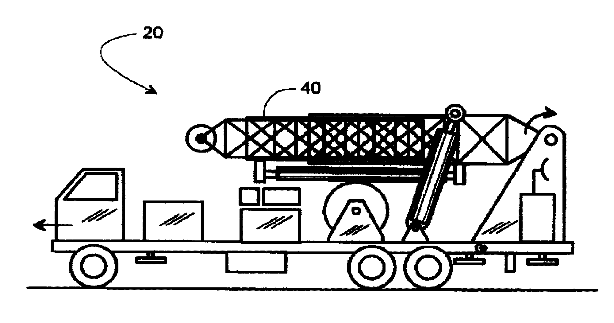
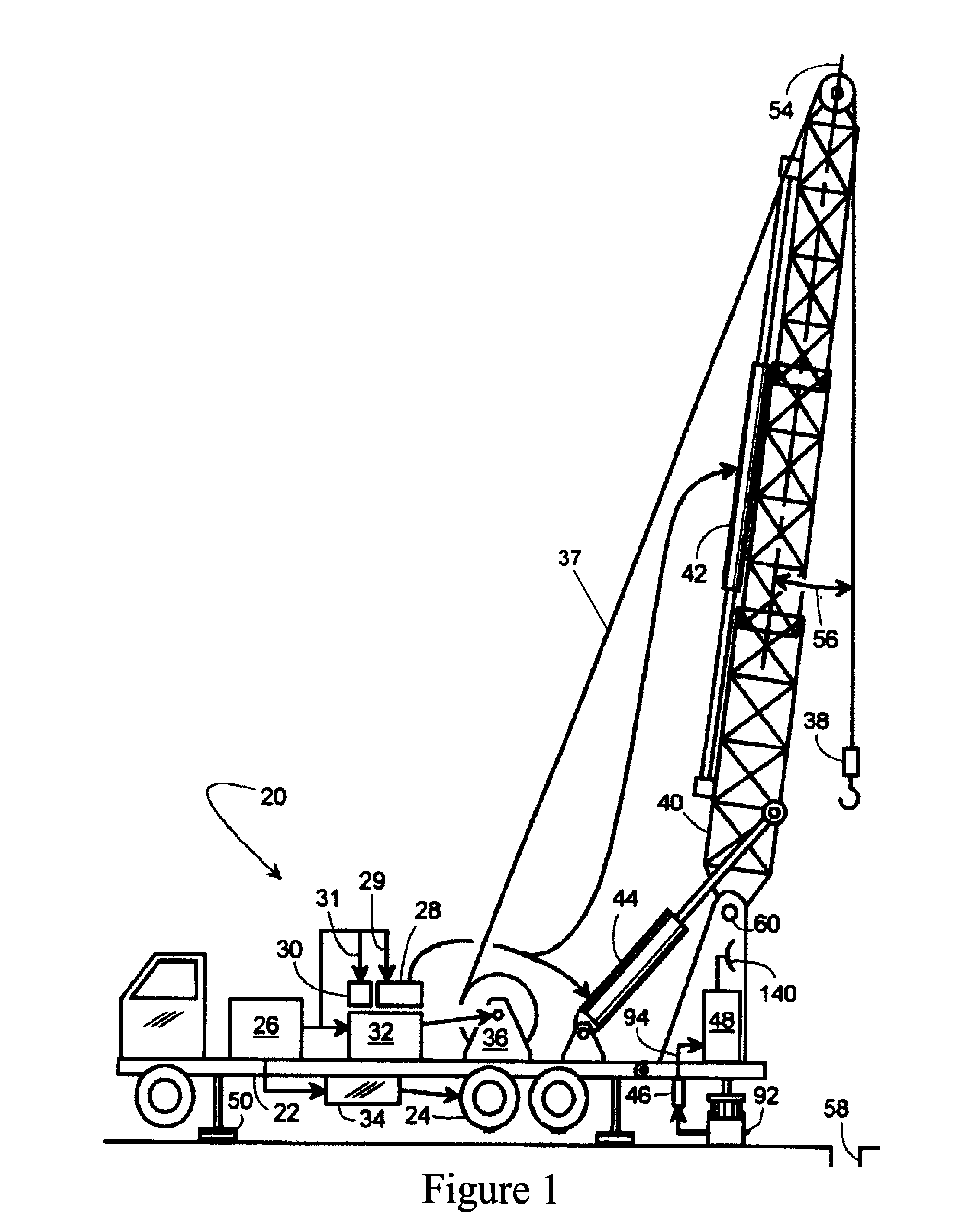
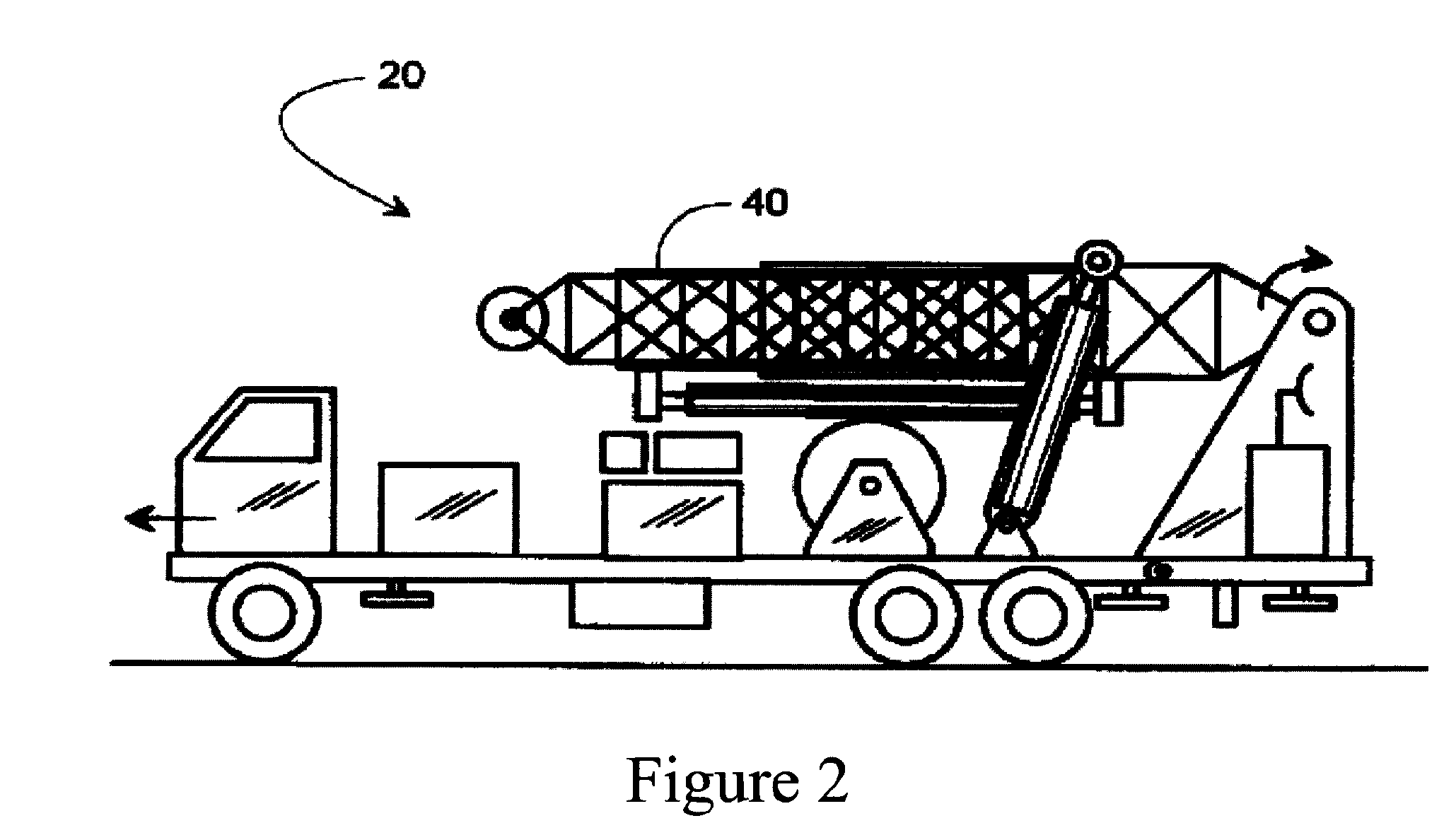
[0026]Exemplary embodiments of the invention will now be described in detail with reference to the included figures. The exemplary embodiments are described in reference to how they might be implemented. In the interest of clarity, not all features of an actual implementation are described herein. Those of ordinary skill in the art will appreciate that in the development of an actual embodiment, several implementation-specific decisions must be made to achieve specific goals, such as compliance with system-related and business-related constraints, which can vary from one implementation to another. Moreover, it will be appreciated that such a development effort might be complex and time-consuming, but would nevertheless be a routine undertaking for those of ordinary skill in the art having benefit of this disclosure. Further aspects and advantages of the various exemplary embodiments will become apparent from consideration of the following description and review of the figures.

[0027]...


PUM


Abstract

A method and system for automatically setting adjusting and monitoring load-based limits is capable of monitoring the hookload, rig weight and combined measured weight and compare those parameters to limits. If any of the hookload, rig weight or measured weight should increase to a level beyond its limit, the system is able to adjust the operation of the well service rig to limit damage to the equipment and danger to the operators and service personnel. The system is also capable of adjusting each of the limits as the weight of the rig and actual hookload change over time while conducting an activity to maintain the respective limits in the most beneficial range.

Description

RELATED APPLICATION[0001]This application claims priority under 35 U.S.C. §119 to U.S. Provisional Patent Application No. 61 / 355,772, titled “System, Methods, and Devices for an Auto Hook Load Limiter,” filed on Jun. 17, 2010, the entire contents of which are hereby fully incorporated herein by reference.TECHNICAL FIELD[0002]The technical field generally pertains to equipment used for servicing wells. More specifically the field of the exemplary embodiments pertains to an analysis of well service rig loads and rig load data to determined hookload and other rig load limits and to monitor the data to determine if overload conditions based on those limits occurs.BACKGROUND OF THE INVENTION[0003]After a well has been drilled, it must be completed before it can produce gas or oil. Once completed, a variety of events may occur to the formation causing the well and its equipment to require a “work-over.” For purposes of this application, “work-over” and “service” operations are used in the...

Claims


Application Information

Patent Timeline
Patent Type & Authority Patents(United States)
IPC IPC(8): G06F19/00
CPCB66C23/42E21B7/022E21B19/08E21B44/00
Inventor BOWEN, JAY CHARLESBURKE, ROGER PHILLIPNEAL, HOWARD ADRIANYORGA, DERREK
Owner KEY ENERGY SERVICES
Why Eureka
Try Eureka