
ECU monitoring system and monitoring method

a technology of electronic control unit and monitoring system, which is applied in the direction of computer control, process and machine control, instruments, etc., can solve the problems of bugs driving the ecus, increasing the speed and impossibility of braking a vehicle, and ecu malfunctions that occur frequently, so as to prevent ecu malfunctions, improve the reliability of the ecu, and prevent damage to property and an injury of a human

Active Publication Date: 2017-06-06
KOREA ELECTRONICS TECH INST
View PDF13 Cites 3 Cited by
  • Summary
  • Abstract
  • Description
  • Claims
  • Application Information

AI Technical Summary

Benefits of technology

The patent text describes a technology that prevents malfunctions in electronic control units (ECUs) caused by unexpected system noise. It does this by detecting the noise at the input of the ECU and producing a stable output in response. This technology also prevents damage to property and injury to humans by preventing sudden starts due to malfunctions in ECUs. Finally, it improves the reliability of the ECU, allowing drivers to drive their vehicles without feeling anxiety.

Problems solved by technology

As seen from the accident due to sudden start of the vehicles by Toyota, damages due to malfunctions of ECUs frequently occur.
The malfunctions of ECUs cause an increase in vehicle speed and impossibility of braking a vehicle, which the driver does not want in driving or starting the vehicle, not only in manual transmission or automatic transmission vehicles, but hybrid vehicles.
The reason of the malfunctions of the ECUs can fall into a software problem and a hardware problem.
The software problem is involved in bugs driving the ECUs in most cases.
It is difficult to find out the reason of the software bugs and it is more difficult to access the information of the ECUs, because the manufacturers of the vehicles are unwilling to open the information for security.
The hardware problem is unaccountable noise generated in ECU connectors (hereafter, referred to as a “system noise”).
The system noise causes a malfunction in the output of the ECUs by generating undesired signals at the input of the ECU.
However, the technologies of monitoring and distinguishing malfunctions in the related art have a problem in that there is a limit in finding out the reasons of problems in an ECU and it is difficult to take measures against other situations except for the acceleration pedal or the brake pedal, because they use the values resulting from analysis of the information outputted by OBD (On Board Diagnostics).

Method used


Image

  • ECU monitoring system and monitoring method
  • ECU monitoring system and monitoring method
  • ECU monitoring system and monitoring method

Examples


Embodiment Construction

[0026]In the following detailed description, only certain exemplary embodiments of the present invention have been shown and described, simply by way of illustration. As those skilled in the art would realize, the described embodiments may be modified in various different ways, all without departing from the spirit or scope of the present invention. Accordingly, the drawings and description are to be regarded as illustrative in nature and not restrictive. Like reference numerals designate like elements throughout the specification.

[0027]ECU monitoring system and method according to an exemplary embodiment of the present invention are described hereafter in detail with the drawings. The present invention, however, is not limited or restricted to the exemplary embodiments.

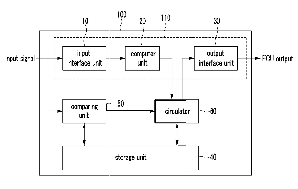
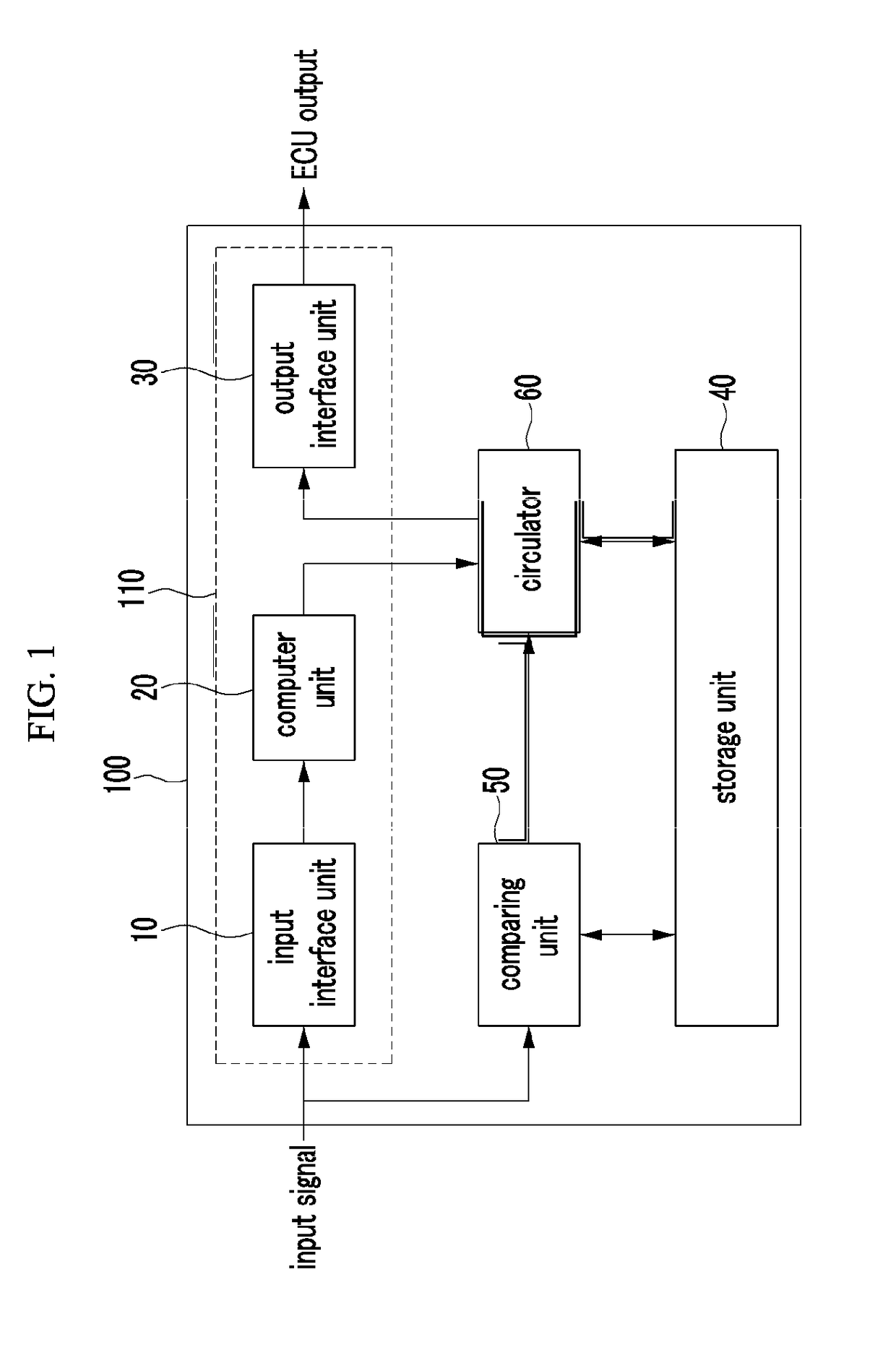
[0028]FIG. 1 is a schematic diagram of an ECU monitoring system according to an exemplary embodiment of the present invention. As shown in FIG. 1, an ECU monitoring system 100 according to an exemplary embodiment of ...


PUM


Abstract

An ECU monitoring system includes: an ECU that includes an input interface unit, a computer unit, and an output interface unit; a storage unit that stores a normal input signal and a normal output signal; a comparing unit that calculates a compared difference by comparing the current input signal with a previous input signal stored in the storage unit, and outputs an alarming signal showing the current input signal is abnormal, when the compared difference is out of a predetermined range; and a circulator that receives the output signal, provides the output signal when the output signal is a normal output signal, and provides a normal output signal to the output interface unit, instead of the output signal outputted from the computer in response to the abnormal input signal, when receiving the alarming signal from the comparing unit.

Description

CROSS REFERENCE TO RELATED APPLICATIONS[0001]This application is a National Stage of International Application No. PCT / KR2012 / 011523 filed Dec. 27, 2012, claiming priority based on Korean Patent Application No. 10-2011-0145502 filed Dec. 29, 2011, the contents of all of which are incorporated herein by reference in their entirety.TECHNICAL FIELD[0002]The present invention relates to an ECU (Electronic Control Unit) monitoring system. More particularly, the present invention relates to an ECU monitoring system that monitors and prevents a malfunction of an ECU by monitoring system noise (for example, clock signals or pulse signals) at the input terminal of the ECU.BACKGROUND ART[0003]Recently, as the vehicles are developed from a manual transmission vehicle to an automatic transmission vehicle and hybrid and electric vehicles, the number of ECUs increases. One vehicle is equipped with ten to no less than a hundred ECUs.[0004]As seen from the accident due to sudden start of the vehicl...

Claims


Application Information

Patent Timeline
Patent Type & Authority Patents(United States)
IPC IPC(8): G05B15/02G06F11/07G06F11/30B60W50/04
CPCG05B15/02B60W50/045G06F11/0739G06F11/0754G06F11/0793G06F11/3013G06F11/3072B60R16/02B60W50/04
Inventor LEE, CHUL DONGKO, JAE JINPARK, SANG HYUNCHOI, HYO SUB
Owner KOREA ELECTRONICS TECH INST
Learn More