Liquid refrigerant transfer tool

a technology for liquid refrigerant and tools, which is applied in the direction of liquid transfer devices, liquid handling, instruments, etc., can solve the problems of adding cost to containers, unnecessary cost associated with spilled liquid, and liquid being spilled from containers, so as to reduce the risk of cfc release into the surrounding area and atmosphere, avoid injury to operators or damage to equipment that could result from moving or inverting containers

Inactive Publication Date: 2006-11-30
IBM CORP
View PDF5 Cites 3 Cited by
  • Summary
  • Abstract
  • Description
  • Claims
  • Application Information

AI Technical Summary

Benefits of technology

[0004] The present invention eliminates the need to invert storage containers and in particular liquid refrigerant drums during the charging process of industrial chillers. Exemplary tools in accordance with the present invention significantly reduce the risk of CFC release into the surrounding area and atmosphere. In addition, injury to operators or damage to equipment that could result from moving or inverting containers is avoided.

Problems solved by technology

Due to the cost associated with these liquids, substantially all of the liquid in a given container is used.
However, installed fittings and valves add cost to the container and can be damaged during shipment.
This procedure, however, can be hazardous and can result in liquid being spilled from the container.
The spilled liquid can represent an unnecessary environmental hazard and could result in an unnecessary cost associated with the spilled liquid.
Tilting presents a potential spill hazard and larger or heavier containers can be difficult to lift and tilt.

Method used


Image

  • Liquid refrigerant transfer tool
  • Liquid refrigerant transfer tool
  • Liquid refrigerant transfer tool

Examples


Embodiment Construction

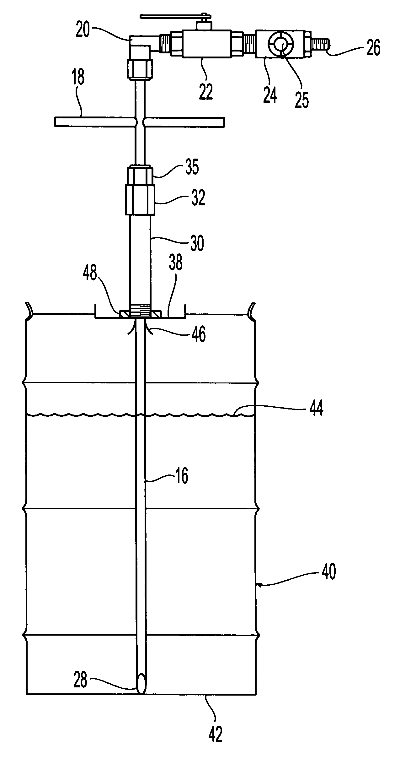
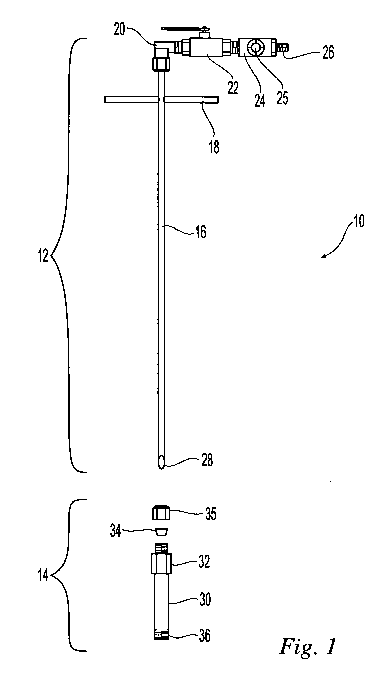
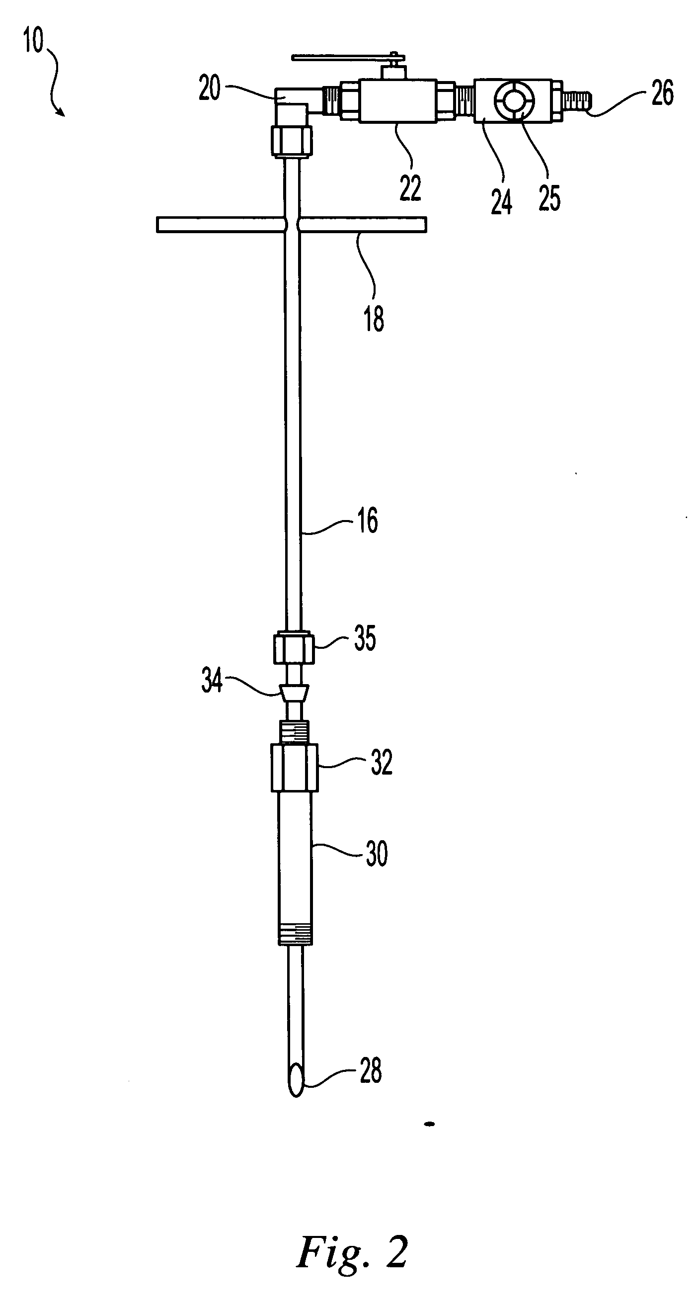
[0014] Referring initially to FIG. 1, an exemplary embodiment of a liquid transfer tool 10 in accordance with the present invention is illustrated. As illustrated, the liquid transfer tool 10 includes two assemblies, a drum or container connection assembly 14 and an extraction tube assembly 12. The container connection assembly 14 is arranged to securely connect the liquid transfer tool 10 to a container or drum and to provide support for the extraction tube assembly 12. In one embodiment, the container connection assembly includes a main body portion 30. In one embodiment, the main body portion is a shaft, tube or piper having an inner diameter that is sufficient to accept the extraction tube assembly. The tube can be fabricated as a custom fitting or can be a standard plumbing fitting, for example a standard male or female nipple. In one embodiment, the main body portion 30 is a ¾ inch national pipe thread (npt) male nipple having a length of about 6 inches. The materials for the ...


PUM


Abstract

A liquid transfer tool is provided that facilitates safe removal or transfer of liquids from containers in the upright position. The tool includes a retractable sealed tube that can pierce a seal and that extends to the bottom of the container to extract substantially all of the liquid disposed in the container.

Description

FIELD OF THE INVENTION [0001] The present invention is directed to the field of plumbing fixtures for liquid transfer. BACKGROUND OF THE INVENTION [0002] Many liquids, for example liquids used in industrial and commercial settings, are stored and dispensed from large containers, for example metal drums, or are transferred between storage containers. Due to the cost associated with these liquids, substantially all of the liquid in a given container is used. Therefore, during transfer or dispensing of these liquids from the container, substantially all of the liquid is removed from the container. All of the liquid can be removed if the container is tapped or drained at or near the bottom. This, however, requires that a fitting and possibly a valve is provided with the container. However, installed fittings and valves add cost to the container and can be damaged during shipment. In addition, the container can be rotated or positioned so that the fitting are not located at the bottom of...

Claims


Application Information

Patent Timeline
Patent Type & Authority Applications(United States)
IPC IPC(8): B67D5/00B67D5/60B67D7/78B67D7/08B67D99/00
CPCB67D7/0288B67B7/24
Inventor O'LEARY, NEILTEDESCO, FREDERICK
Owner IBM CORP
Why Eureka
Try Eureka