Portable, self-sustaining power station

a self-sustaining, portable technology, applied in wind energy generation, thermal-pv hybrid energy generation, wind motors with parallel air flow, etc., can solve the problems of survivors not being able to reach relief supplies, inability to immediately deploy relief supplies, and inability to reach survivors. , to achieve the effect of enhancing stability of the station

Active Publication Date: 2013-11-26
BRISBEN WATER SOLUTIONS
View PDF78 Cites 49 Cited by
  • Summary
  • Abstract
  • Description
  • Claims
  • Application Information

AI Technical Summary

Benefits of technology

[0012]Another objective of the present invention is to provide a power station that includes a solar panel array that is mounted on a roller assembly that can be quickly and easily deployed by a single person.
[0016]Still another objective of the present invention is to teach solar panels which are symmetrically arranged solar panels when in the deployed position to provide enhanced stability to the station, especially during windy conditions.

Problems solved by technology

It became readily apparent that certain deficiencies persisted in treating large-scale disasters, including the lack of specifically designed equipment capable of being immediately deployed into disaster areas to supply basic needs for the inhabitants, such as water, electricity, telecommunications, etc.
Such inadequacies include the inability of the survivors to reach relief supplies, the inability of the relief supplies to reach the survivors, and the lack of facilities to help the survivors and / or workers rebuild the infrastructure.
Similar problems locating potable water and electricity are encountered daily by the inhabitants of developing and third world countries and / or those countries currently at war.
However, survivors could not reach the location where the equipment was placed.
However, these fossil fuels must be constantly replenished and their combustion releases harmful pollutants into the environment.
None of the aforementioned prior art disclose the space saving arrangement of solar panels in the stowed position on top of the container of the inventive station.
Nor does the prior art teach or suggest symmetrically arranging the solar panels in the deployed position to enhance the stability of the station.

Method used


Image

  • Portable, self-sustaining power station
  • Portable, self-sustaining power station
  • Portable, self-sustaining power station

Examples


Embodiment Construction

[0039]Detailed embodiments of the instant invention are disclosed herein, however, it is to be understood that the disclosed embodiments are merely exemplary of the invention, which may be embodied in various forms. Therefore, specific functional and structural details disclosed herein are not to be interpreted as limiting, but merely as a basis for the claims and as a representation basis for teaching one skilled in the art to variously employ the present invention in virtually any appropriately detailed structure.

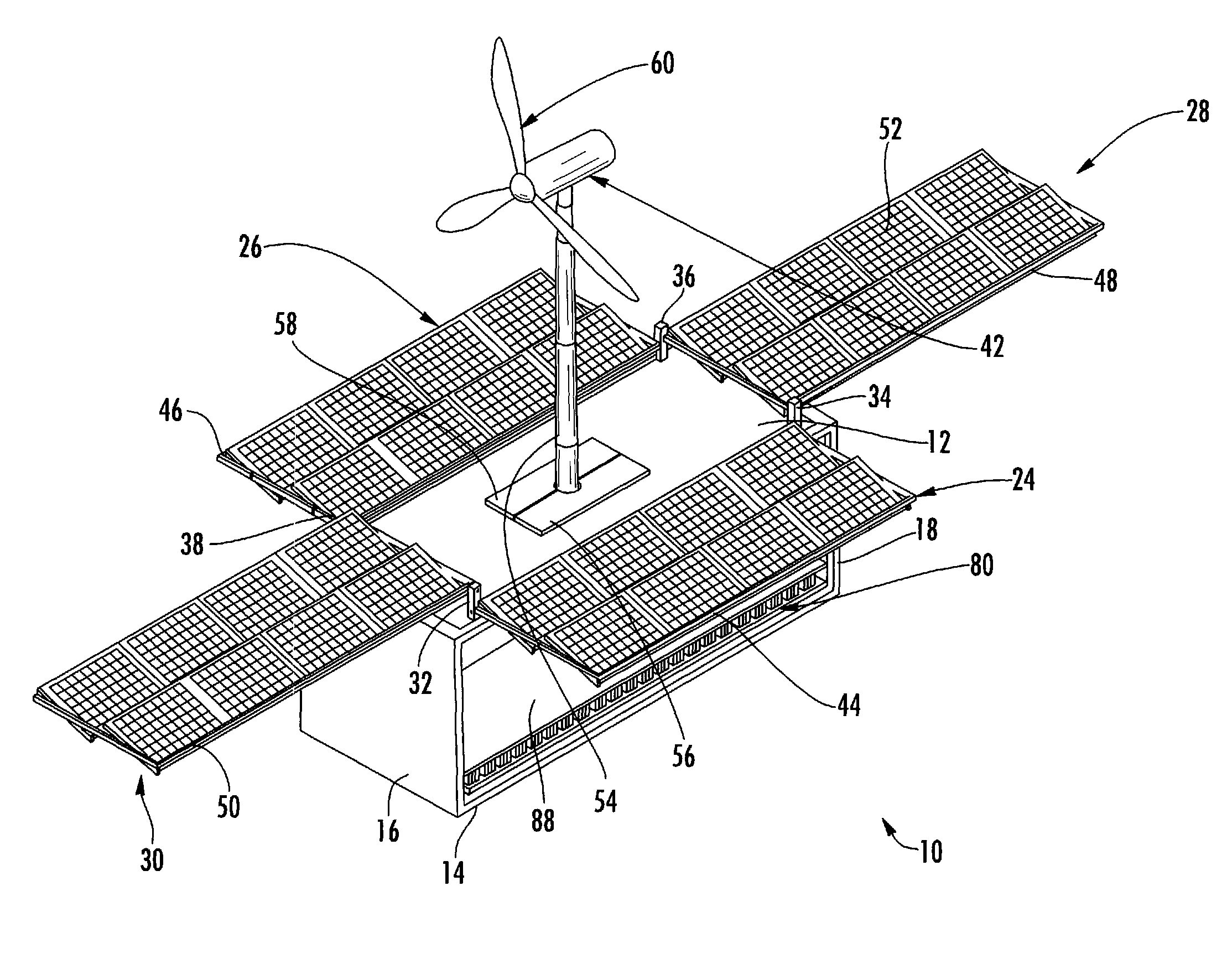
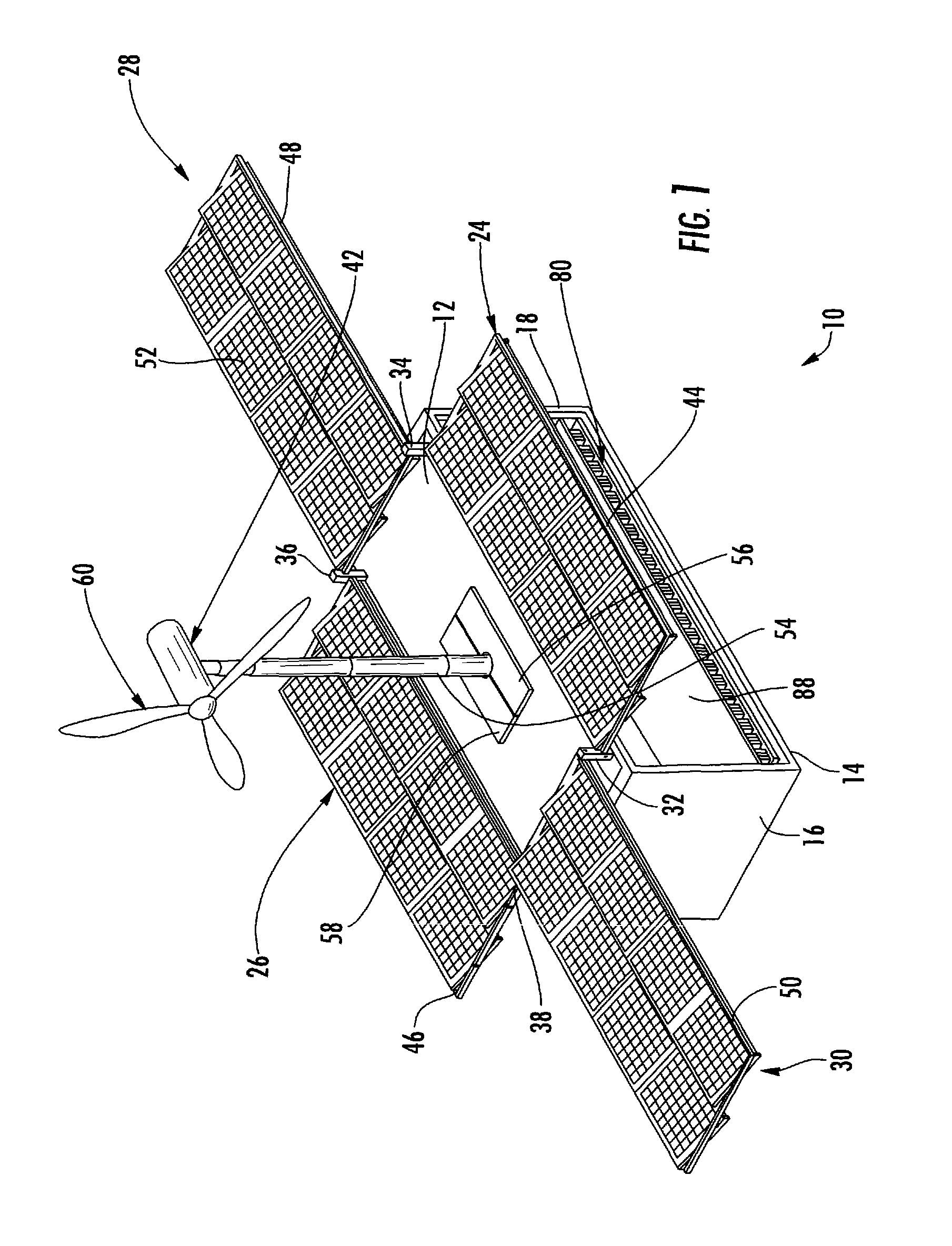
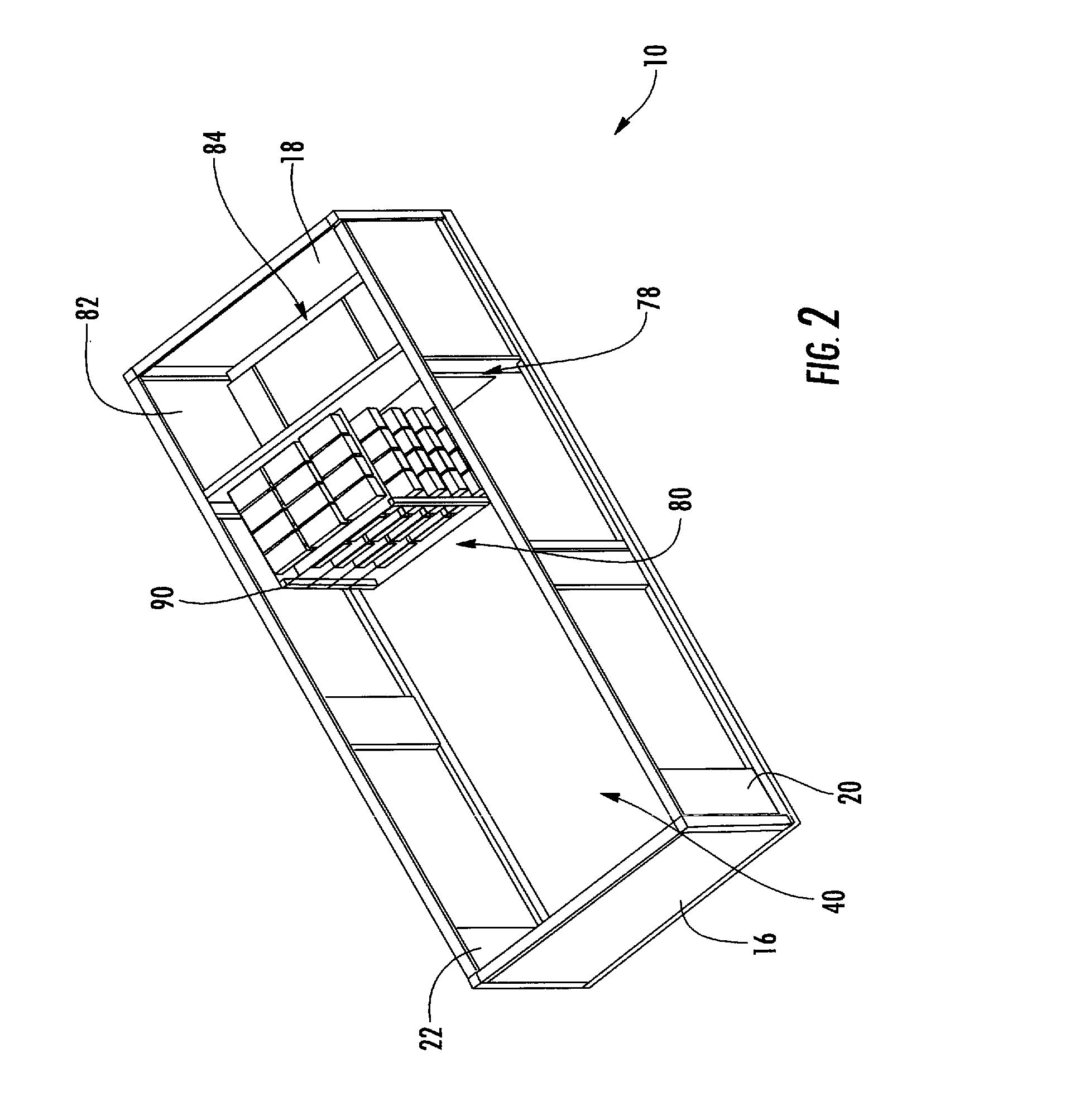
[0040]Referring now to FIGS. 1-9, wherein like elements are numbered consistently throughout, FIG. 1 illustrates one embodiment of the inventive power station, generally referenced as 10. The station is in the form of a container with a top panel 12, bottom panel 14, two pairs of oppositely disposed sidewall panels (16, 18) (20, 22) forming an interior chamber 40. Although depicted here as a rectangular station, is it within the purview of the invention to provide a stati...


PUM

PropertyMeasurementUnit
sizeaaaaaaaaaa
sizesaaaaaaaaaa
sizesaaaaaaaaaa

Abstract

A self-sustaining, portable, power station that may be moved by land, air, or sea to an area that has no utilities. The station is provided with solar panel arrays in communication with at least one electrical distribution and storage means. The derived electricity is used to power various systems including, albeit not limited to, a communications system, a water filtration system, a water distribution system to allow the public to draw potable water and provide basic hygiene. The electricity derived may also be used to run outside systems, such as schools, hospitals, or the like. The solar panel arrays are mounted on roller assemblies that can be easily slide between a stowed and deployed condition. The solar arrays include a plurality of solar panels that are supported by one or more hydraulic actuators to counter balance the weight of the solar panel whereby the solar panel can be easily positioned into the desired tilted orientation.

Description

CROSS REFERENCE TO RELATED APPLICATIONS[0001]This application is a continuation-in-part of U.S. patent application Ser. No. 11 / 965,422, entitled “Portable Self-Sustaining Power Station”, filed on Dec. 27, 2007, which claims benefit of the filing date of U.S. Provisional Patent Application No. 60 / 882,054, filed Dec. 27, 2006, the entire contents of these applications are expressly incorporated herein.FIELD OF THE INVENTION[0002]This invention relates to a portable and self-sustaining power station; particularly, to a power station for producing and distributing electrical power, potable water, and other services to areas that have no operating utilities.BACKGROUND OF THE INVENTION[0003]In the aftermath of the disastrous events of Sep. 11, 2001 and hurricane Katrina, the emergency response capability of most governmental agencies charged with such a mission has undergone a thorough review. After reviewing the tools and programs available to emergency response agencies (police, fire an...

Claims


Application Information

Patent Timeline
Patent Type & Authority Patents(United States)
IPC IPC(8): H01M10/44
CPCF03D1/005F03D9/007F03D11/04H02S20/00H02S30/20H02S10/10Y02E10/50Y02E10/728F03D9/11F03D9/25F03D13/20F03D13/40F24S25/33F24S30/425F24S2025/018F24S2030/115H02S10/12H02S10/40H02S20/30H02S40/44Y02E10/47Y02E10/60Y02E10/72Y02E70/30
Inventor MCGUIRE, DENNISJAKHETE, SANJEEV
Owner BRISBEN WATER SOLUTIONS
Why Eureka
Try Eureka